OFDM transmit signal receiver

a transmit signal and receiver technology, applied in the field of receivers for receiving ofdm (orthogonal frequency division multiple) transmit signals, can solve the problems of limiting the detection range, wasting a long time to detect the reception quality signal, and wasting detection-unit tim

Active Publication Date: 2006-01-03
KK TOSHIBA
View PDF15 Cites 13 Cited by
  • Summary
  • Abstract
  • Description
  • Claims
  • Application Information

AI Technical Summary

Benefits of technology

[0010]An OFDM transmit signal receiver according to an aspect of the present invention comprises: a demodulation circuit receiving an OFDM transmit signal containing an information carrier, an additive-information transmission carrier, and a reception-synchronization pilot signal to convert the information carrier, the additive-information transmission carrier, and the reception-synchronization pilot signal into frequency-axial data, the information carrier transmitting information data, the additive-information transmission carrier having a lower multi-valued modulation degree than the information carrier, and the reception-synchronization pilot signal having a lower multi-v...

Problems solved by technology

The method by use of a bit error rate, however, has a problem that an attempt to detect a good reception state reduces errors in a received signal to thereby prolong a detection-unit time in which the number of samples required to detect a bit error rate is detected, thus spending rather a long time to detect the reception-quality signal.
In the terrestrial digital broadcasting by use of the OFDM transmission system, as the modulation method is prescribed a QPSK ...

Method used


Image

  • OFDM transmit signal receiver
  • OFDM transmit signal receiver
  • OFDM transmit signal receiver

Examples


first embodiment

[0023]The following will describe an Orthogonal Frequency Division Multiple transmit signal receiver (hereinafter abbreviated as OFDM transmit signal receiver) according to the first embodiment of the present invention.

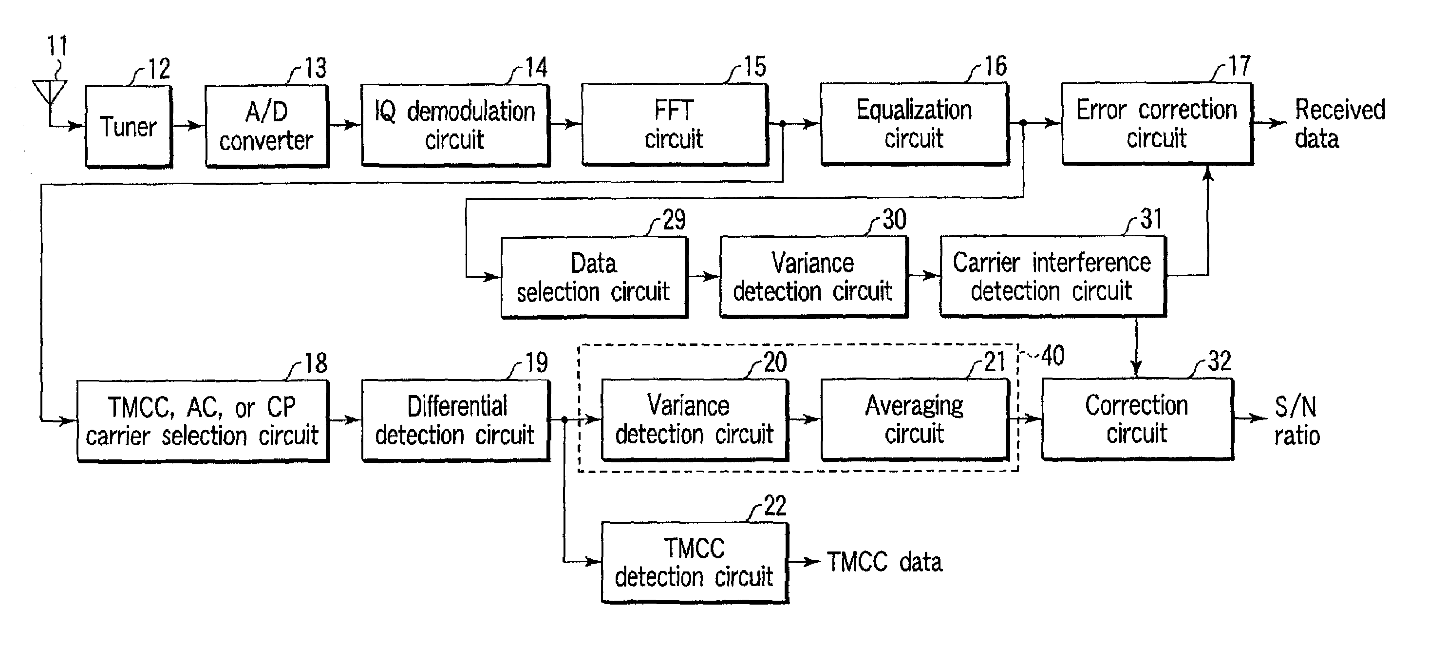
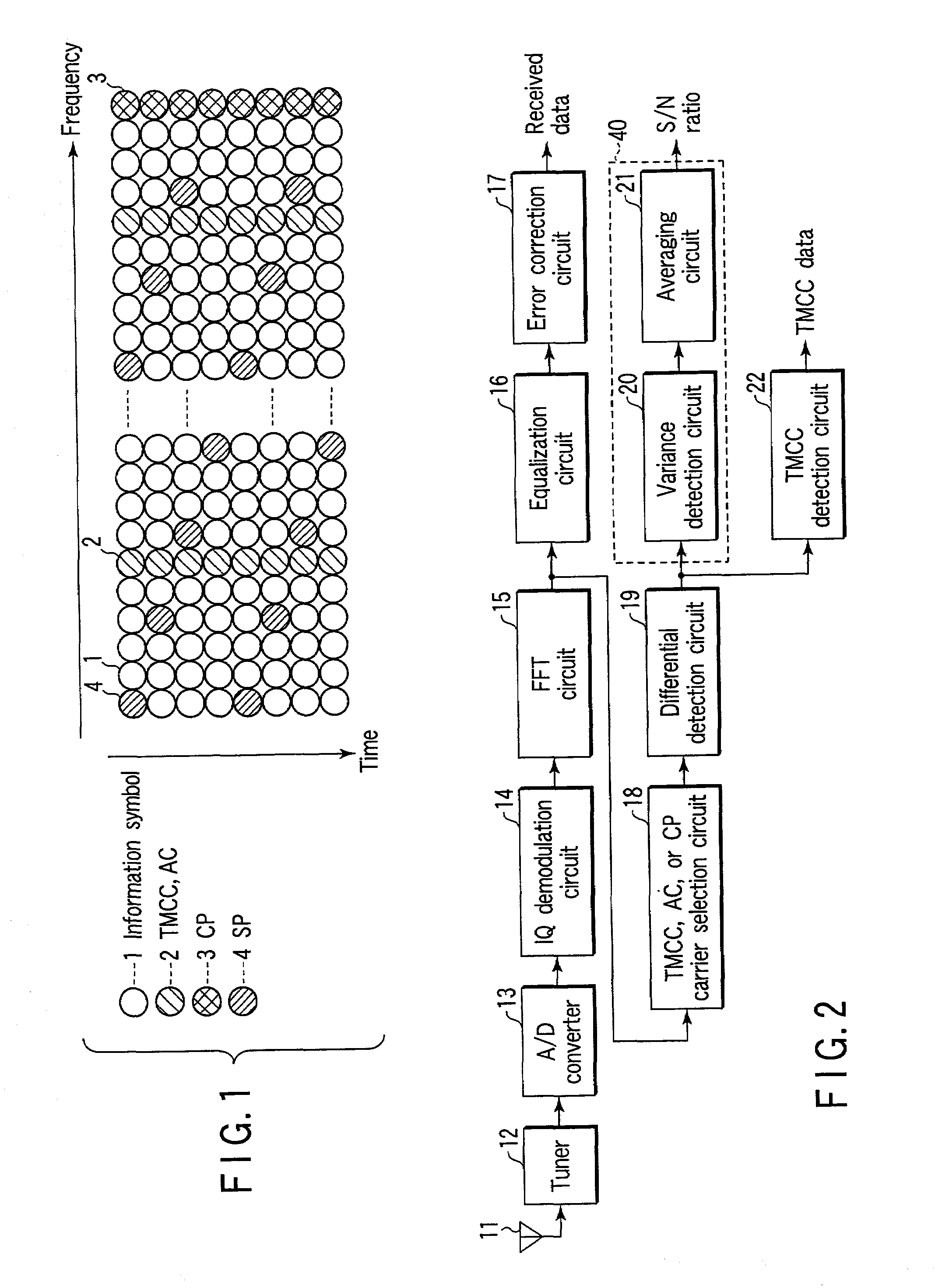
[0024]FIG. 2 is a block diagram for showing a configuration of an OFDM transmit signal receiver according to the first embodiment.

[0025]In FIG. 2, OFDM transmit signals received at an antenna 11 are input to a tuner 12, which then selects such an OFDM transmit signal of these that is of a predetermined channel and converts it into an IF (intermediate frequency) band signal. An output of the tuner 12 is supplied to an analog / digital converter (A / D converter) 13, which then converts it into a digital signal.

[0026]An output of the A / D converter 13 is supplied to an IQ demodulation circuit 14. The IQ demodulation circuit 14 is comprised of a quadrature detection circuit, which serves to detect the output of the A / D converter 13 in a quasi-synchronous orthogonal manner and...

second embodiment

[0036]The following will describe the OFDM transmit signal receiver according to the second embodiment of the present invention.

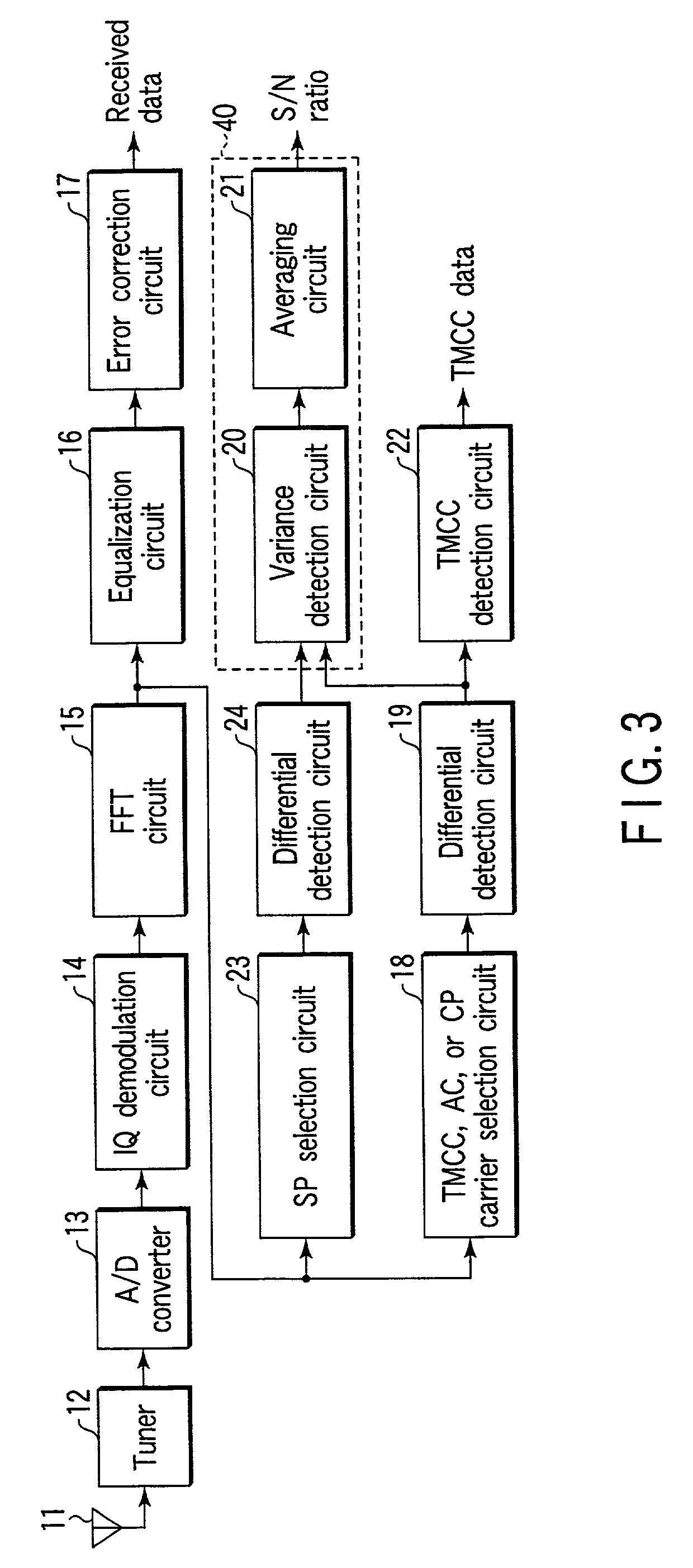
[0037]FIG. 3 is a block diagram for showing a configuration of the OFDM transmit signal receiver according to the second embodiment. In addition to the configuration of the first embodiment shown in FIG. 2, the OFDM transmit signal receiver of this second embodiment has an SP selection circuit 23 for detecting an S / N ratio of a received signal using the SP signal 4 and a differential detection circuit 24. The same components as those of the first embodiment are indicated by the same reference numerals and so their explanation is omitted to describe only the different components as follows.

[0038]As shown in FIG. 3, an output of the above-mentioned FFT circuit 15 branches to be supplied to the SP selection circuit 23. The SP selection circuit 23 selects only the SP signal shown in FIG. 1 and supplies it to the differential detection circuit 24. The differenti...

third embodiment

[0045]The following will describe the OFDM transmit signal receiver according to the third embodiment of the present invention.

[0046]FIG. 4 is a block diagram for showing a configuration of the OFDM transmit signal receiver of the third embodiment. In addition to the configuration of the first embodiment shown in FIG. 2, the OFDM transmit signal receiver of the third embodiment has a data selection circuit 25 for using information symbol 1 to detect an S / N ratio of a received signal, a variance detection circuit 26, an averaging circuit 27, and a selection circuit 28 for selecting either one of an S / N ratio detected using information symbol 1 and that detected using the TMCC and AC carriers 2 and the CP carrier 3. The same components as those of the first embodiment are indicated by the same reference numerals and so their explanation is omitted to describe only the different components as follows.

[0047]As shown in FIG. 4, an output of the above-mentioned equalization circuit 16 bra...


PUM


Abstract

A demodulation circuit receives an OFDM transmit signal containing an information carrier, an additive-information transmission carrier, and a reception-synchronization pilot signal to convert these carriers and signal into frequency-axial data. The information carrier transmits information data. The additive-information transmission carrier and the reception-synchronization pilot signal have a lower multi-valued modulation degree than the information carrier. A differential detection circuit conducts detection processing by using a detection-subject symbol of a plurality of symbols indicated at a predetermined interval in the same frequency range and a symbol ahead that detection-subject symbol by a predetermined time in either one output of the additive-information transmission carrier and the reception-synchronization pilot signal output from the demodulation circuit. A first S/N ratio generating circuit generates an S/N ratio based on a detection output provided from the differential detection circuit. The S/N ratio indicates the reception quality of the OFDM transmit signal.

Description

CROSS-REFERENCE TO RELATED APPLICATIONS[0001]This application is based upon and claims the benefit of priority from the prior Japanese Patent Application No. 2000-351611, filed Nov. 17, 2000, the entire contents of which are incorporated herein by reference.BACKGROUND OF THE INVENTION[0002]1. Field of the Invention[0003]The present invention relates to a receiver for receiving an OFDM (Orthogonal Frequency Division Multiple) transmit signal, and more particularly, it relates to improvement in the detection of a reception quality signal used particularly in antenna adjustment.[0004]2. Description of the Related Art[0005]Recently, a digital transmission system by use of an OFDM transmit signal has been put to practical use especially in a field of terrestrial digital broadcasting. The OFDM method acts to allocate data to a plurality of mutually orthogonal carriers (carrier waves) for modulation and demodulation, by which a transmission side conducts reverse FFT (Fast Fourier Transfer)...

Claims


Application Information

Patent Timeline
IPC IPC(8): H03K9/00H04L1/20H04J11/00H04L27/26
CPCH04L27/2647H04L1/20
Inventor SEKI, TAKASHIKOYAMA, TAKESHI
Owner KK TOSHIBA
Why Eureka
Try Eureka