Time resolved computed tomography angiography

a computed tomography and time-resolved technology, applied in the field of computed tomography, can solve the problems of low signal-to-noise ratio, sensitivity to artifacts of patient motion, and the requirement for a significant load of contrast agent to be inserted in the patient, so as to reduce the invasiveness and discomfort of the procedure for the patient, and remove timing uncertainties

Inactive Publication Date: 2006-01-03
WISCONSIN ALUMNI RES FOUND
View PDF9 Cites 41 Cited by
  • Summary
  • Abstract
  • Description
  • Claims
  • Application Information

AI Technical Summary

Benefits of technology

[0009]The present invention is a method for producing time resolved angiograms following injection of a contrast agent using a high speed computed tomography system. The contrast agent can be injected through typical arterial injection, or intravenously, thereby reducing the invasiveness and discomfort of the procedure for the patient. The method of the present invention is used to acquire a time series of computed tomographic angiography (CTA) images rather than a single CTA image, thereby removing timing uncertainties found in typical CTA.

Problems solved by technology

Although a number of angiographic imaging modalities are available, all of these known methods suffer from one or more disadvantages including sensitivity to artifacts from patient motion, low signal to noise ratio, and the requirement for a significant load of contrast agent to be inserted in the patient.
Furthermore, although DSA had been developed with the hope of using it to perform intravenous contrast imaging, which is less invasive and less uncomfortable for the patient than arterial injection, attempts to provide such a system have been generally unsuccessful.
These streak artifacts preclude the use of this CRA method for intravenous angiography because of the reduced vasculature contrast provided by this contrast injection method.

Method used


Image

  • Time resolved computed tomography angiography
  • Time resolved computed tomography angiography
  • Time resolved computed tomography angiography

Examples


first embodiment

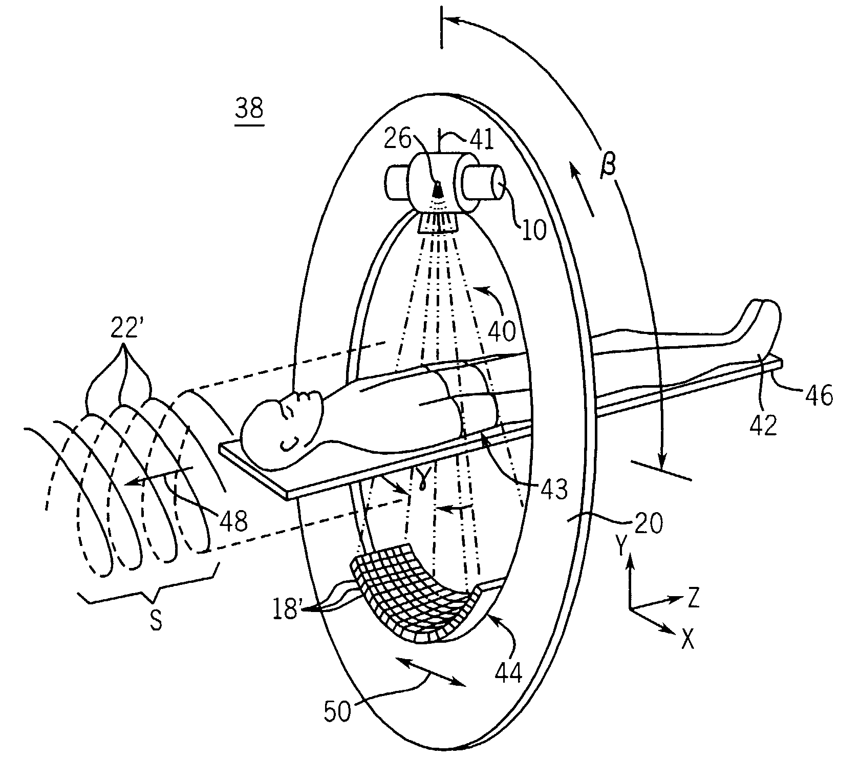
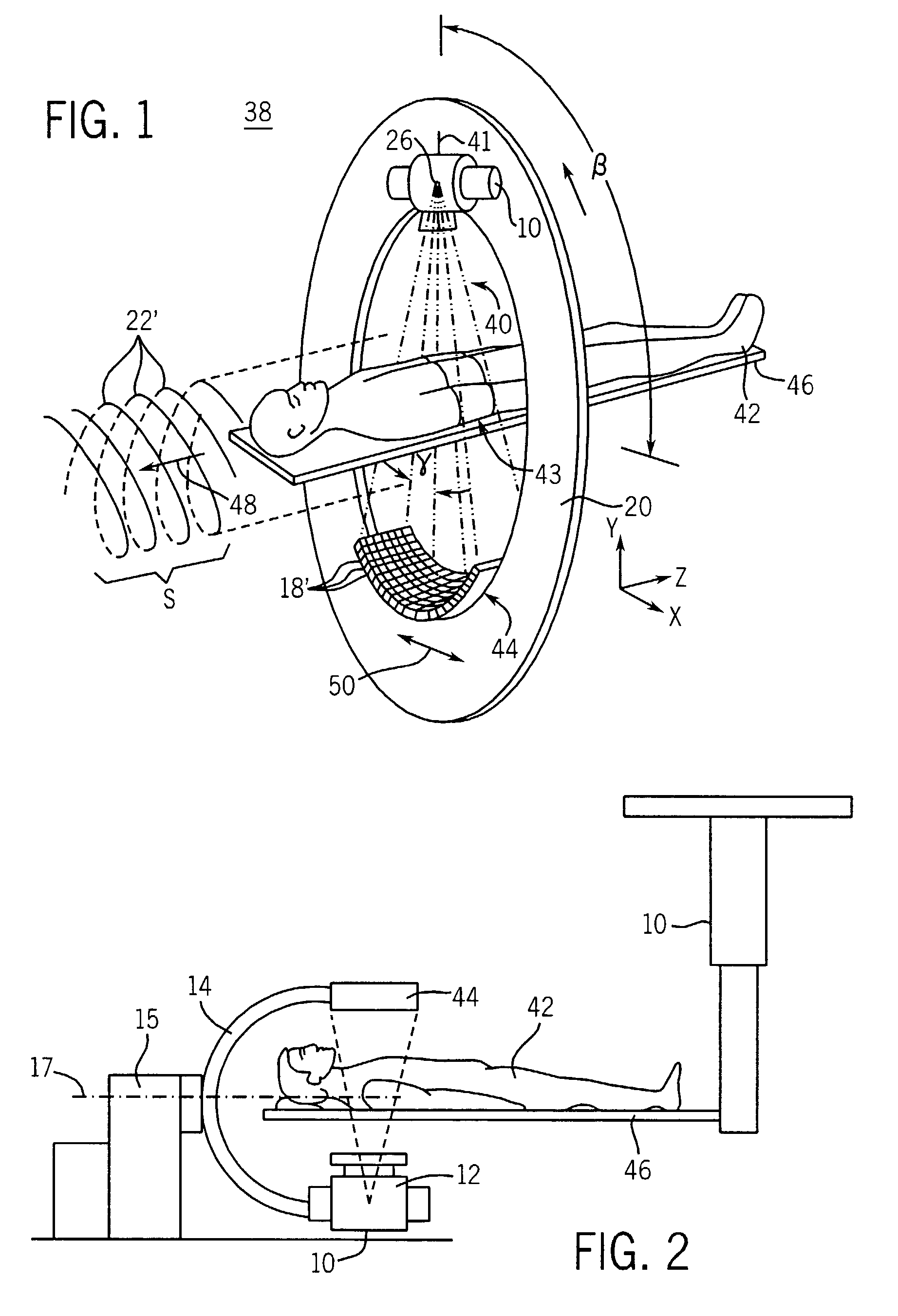
[0020]Referring now to FIG. 1, a first embodiment CT scanner which employs the present invention includes a gantry 20 having an opening that defines an imaging area (not separately numbered) where gantry 20 supports an x-ray source 10 oriented to project a fan beam 40 of x-rays along a beam axis 41 through a patient 42 to an opposed two-dimensional detector array 44. The gantry 20 rotates to swing the beam axis 41 within a gantry plane 38 defining the x-y plane of a Cartesian coordinate system. Rotation of gantry 20 is measured by beam angle β from an arbitrary reference position within the gantry plane 38.

[0021]A patient 42 rests on a patient support table 46 which may be moved along a translation axis 48 aligned with a Z-axis of the Cartesian coordinate system. Table 46 passes through gantry plane 38 and is radio-translucent so as not to interfere with the imaging process.

[0022]The x-rays of the fan beam 40 diverge from the beam axis 41 within the gantry plane 38 across a transver...

second embodiment

[0024]Referring now to FIG. 2, a CT scanner which employs the present invention comprises a C-arm 14 to which the two-dimensional detector 44 and X-ray source 12 are mounted. Here, again the patient 42 is positioned on a table 46. The C-arm 14 is rotationally mounted to a base 15, and data for the generation of three-dimensional images is obtained by rotating the X-ray source 12 and detector 44 around a defined axis 17. CT scanners of the type shown in FIG. 2 are particularly useful in angiography, as described in Use of a C-Arm system to generate True 3D Computed Tomography Rotational Angiograms: Preliminary in vitro and In vivo Results. R. Fahrig, S. Lownie, and D W Holdsworth, AJNR 18:1507–154, September 1997.

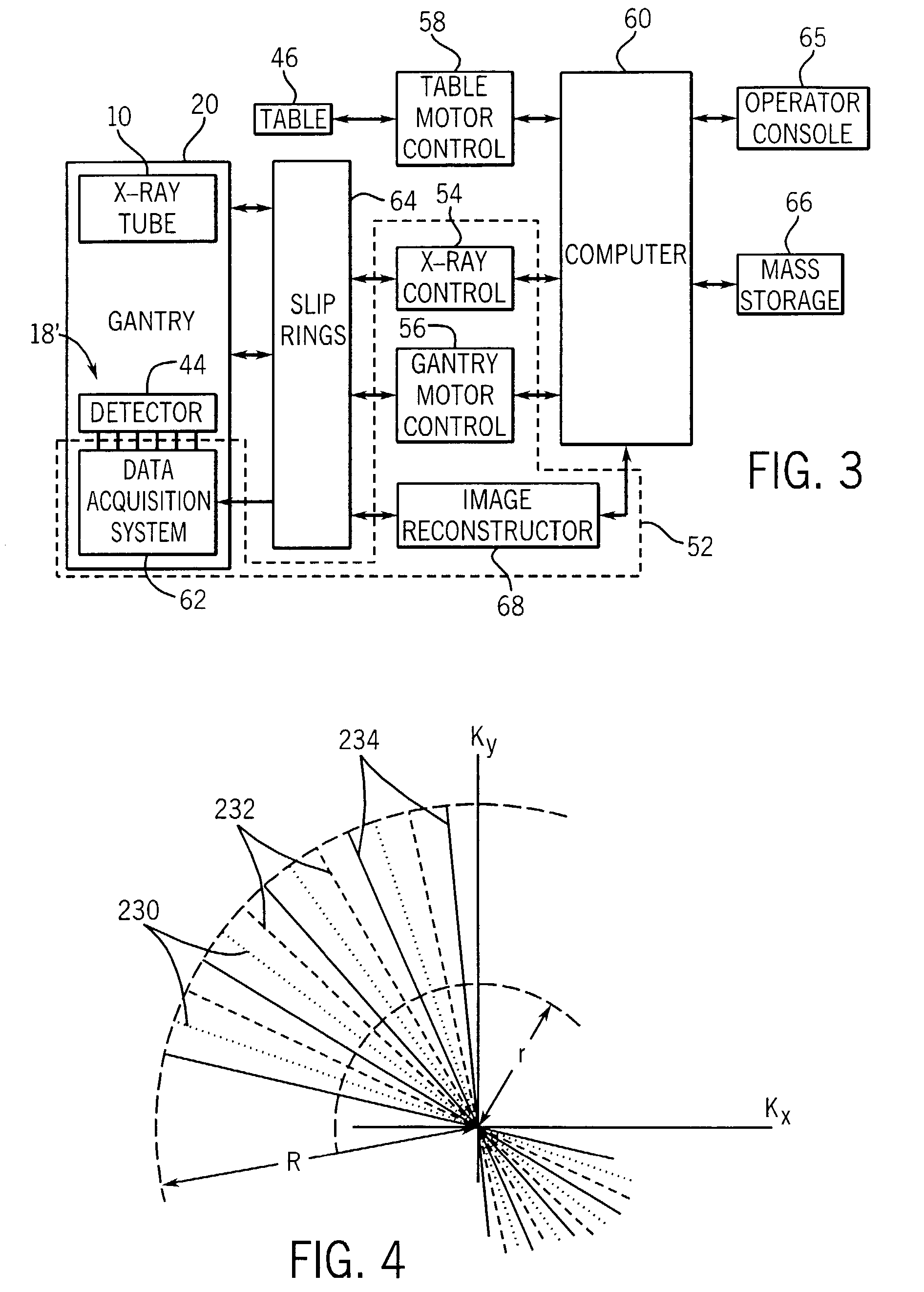
[0025]Referring now to FIG. 3, an exemplary control system for controlling the CT imaging system of FIG. 1 or 2 includes a plurality of imaging control modules 52, a table motor control 58, a computer 60, an operator's console 65 and a mass storage device 66. The imaging con...


PUM


Abstract

A contrast enhanced dynamic study of a subject is performed with a CT system. A series of undersampled image data sets are acquired during the study with successive data sets acquired at interleaved projection angles. More fully sampled image data sets are formed by transforming the x-ray attenuation projection data to k-space and then sharing peripheral k-space data between undersampled k-space data sets. Artifacts due to undersampling are thus reduced without significantly affecting the time resolution of a series of reconstructed images.

Description

CROSS-REFERENCE TO RELATED APPLICATIONS[0001]This application claims the benefit of U.S. Provisional Patent Application No. 60 / 348,110 filed Nov. 9, 2001 and is a continuation-in-part of U.S. patent application Ser. No. 09 / 767,757 filed on Jan. 23, 2001, now U.S. Pat. No. 6,487,435, which is a continuation-in-part of U.S. patent application Ser. No. 09 / 600,433 filed on Jan. 10, 2001, now U.S. Pat. No. 6,630,828, which is the national phase of PCT Application No. US98 / 26523 filed on Dec. 11, 1998, which has the benefit of earlier filed U.S. Provisional Patent Application No. 60 / 081,409 filed on Apr. 10, 1998. This application is also a continuation-in-part of PCT Application No. US01 / 08477 filed on Mar. 16, 2001, which has the benefit of earlier field U.S. Provisional Patent Application No. 60 / 193,088 filed on Mar. 30, 2000, which in turn is a continuation-in-part of U.S. patent application Ser. No. 09 / 314,227 filed on May 18, 1999, now U.S. Pat. No. 6,381,486, which claims the benef...

Claims


Application Information

Patent Timeline
Patent Type & Authority Patents(United States)
IPC IPC(8): A61B5/05A61B6/00A61B6/03G01R33/28G01R33/54G01R33/56G01R33/561G01R33/563G06T11/00G16H30/20
CPCA61B6/032A61B6/469A61B6/481A61B6/504G01R33/4824G01R33/5635G06F19/321G06F19/3437G06T11/005G01R33/281G06T2211/404G01R33/5619G01R33/561G16H50/50G16H30/20
Inventor MISTRETTA, CHARLES A.
Owner WISCONSIN ALUMNI RES FOUND
Why Eureka
Try Eureka