Random pattern weight control by pseudo random bit pattern generator initialization

a random bit pattern and weight control technology, applied in the direction of pulse generation with predetermined statistical distribution, error detection/correction, instruments, etc., can solve the problems of large number of deterministic test patterns, need for self-testing technology, and large integrated circuit devices. achieve the effect of less chip area

Inactive Publication Date: 2006-01-03
IBM CORP
View PDF6 Cites 10 Cited by
  • Summary
  • Abstract
  • Description
  • Claims
  • Application Information

AI Technical Summary

Benefits of technology

[0014]The advantage is that the resulting weight factor of the output-pattern is controlled by the initial state of the plurality of PRPGs, and that no further control logic and control lines are needed, as it was mentioned above. Thus, a considerable amount of chip area is saved compared to prior art and easier control of the random weighting is provided. The inventive basic approach can be implemented in any scan designs, LSSD, boundary scan, stumps and Multiple Input Signature Register (MISR) architectures.
[0023]In another special implementation the plurality of the PRPGs may be a combination of LFSRs and ring shift registers (RSR). RSRs have the property, that the initial bit values, here called “initial weight-state”, are not scrambled but shifted over the bit positions generating a weight-pattern. The initial weight-state can be defined in any distribution of the 0 / 1-values. Thus, it can be defined with regard to special characteristics of the device under test in order to enhance test efficiency.

Problems solved by technology

The need for self-test technology is present due to the fact that complex very large-scale integrated circuit devices are fabricated on a single semiconductor chip and contain millions of functional circuit elements.
For testing all these circuit elements, a very huge number of deterministic test patterns are necessary.
While one could apply that number of different input patterns, record the output responses, and compare those responses with the responses that ought to result, this would be an unacceptable work as it would last much too long and is thus impossible for a modern production testing.
A disadvantage of this prior art approach is that a lot of chip area is required for implementing the control circuit 14 and the additional wiring of the control lines.
This disadvantage is the more intolerable the wider are decoders or multiplexers which must be tested with a wide sequence of “0” or “1” bit in parallel, as in such cases the control overhead is consuming an intolerable fraction of chip area.

Method used


Image

  • Random pattern weight control by pseudo random bit pattern generator initialization
  • Random pattern weight control by pseudo random bit pattern generator initialization
  • Random pattern weight control by pseudo random bit pattern generator initialization

Examples


example

LFSR Configuration and Calculated Loops Counts

[0049]

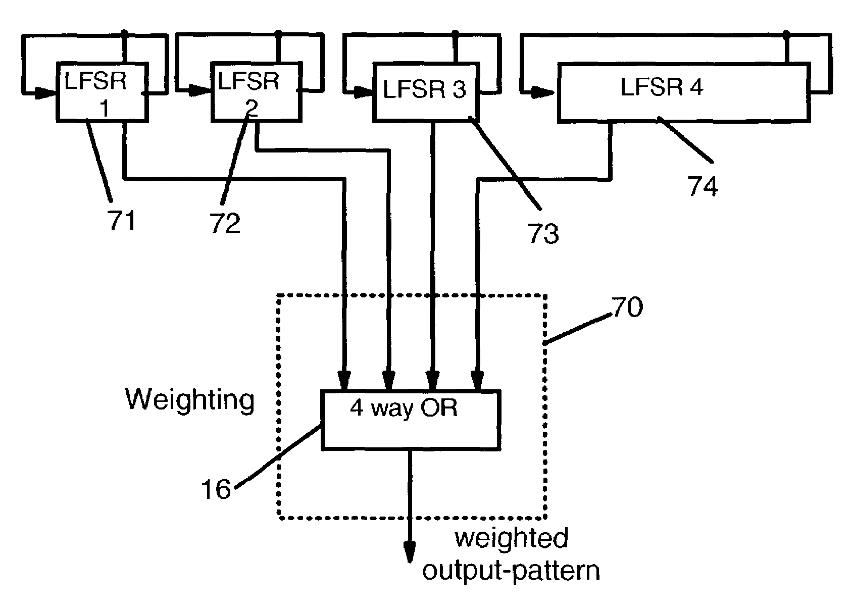
LFSR 1 =  7 Bit,2{circumflex over ( )}7 − 1 = 127,127 = prime numberLFSR 2 =  9 Bit,2{circumflex over ( )}9 − 1 = 511,511 = 7 * 73LFSR 3 = 11 Bit,2{circumflex over ( )}11 − 1 = 2047,2047 = 23 * 89LFSR 4 = 34 Bit,2{circumflex over ( )}34 − 1 = 17179869183,17179869183 =3 * 43691 * 131071;

[0050]The total output-pattern count for this sample plurality of LFSRs is calculated as follows:

127*511*2047*17179869183 cycles=2.2822 E18 cycles.

[0051]In comparison to a single LFSR with the same number (61) of latches the pattern repeats after 2^61−1=2305843009213693951=2.3058 E18 cycles.

[0052]To switch the weighting from mostly ‘1’ to mostly ‘0’, an XOR-gate could be connected behind the OR-gate for building the complement of the output-pattern.

[0053]If one or more LFSRs is switched off by zero-state, the total output-pattern count is calculated as follows:

LFSR2, LFSR3 and LFSR4 running:

Total count=511*2047*17179869183=1.79704 E16

LFSR3 and LFSR4 ...


PUM


Abstract

A plurality of pseudo random bit-pattern generators (PRPGs), advantageously linear feedback shift registers (LFSRs), having predetermined lengths and individual different tap locations for providing a respective sequence of pseudorandom bit-patterns. An output from a predetermined respective tap location at each LFSR is fed to a common OR-gate, a selected subset of the LFSRs are initialized with all bit storing locations to “0” in order to generate a respective permanent “0”-bit sequence, and the output of the OR-gate is used for reading the weighted or flat random bit output-pattern thereof. By controlling the number of zero-set LFSRs—a subset of the LFSRs—the weight of the generated output-pattern can be controlled.

Description

BACKGROUND OF THE INVENTION:[0001]The present invention relates to the generation of random patterns in electronic circuits. In particular, it relates to a method and system for controlling the weight of a random bit pattern generated in an electronic circuit.[0002]A technical area in which the present invention can be preferably applied is in integrated circuits, which are provided with logic circuits and self-test circuits for testing the logic circuits. Such built-in self-test technology is used in a wide spread plurality of technical devices, which have a more or less chip-controlled operation mode. Examples are chips in a motherboard of a computer, printers, and other electronic devices. The need for self-test technology is present due to the fact that complex very large-scale integrated circuit devices are fabricated on a single semiconductor chip and contain millions of functional circuit elements. For testing all these circuit elements, a very huge number of deterministic te...

Claims


Application Information

Patent Timeline
Patent Type & Authority Patents(United States)
IPC IPC(8): G01R31/28G06F11/00H03K3/84
CPCH03K3/84
Inventor APPINGER, JOERG GEORGKESSLER, MICHAEL JUERGENSCHMIDT, MANFRED
Owner IBM CORP
Why Eureka
Try Eureka