Electric power tool with improved speed change gearing

a technology of speed change gearing and electric power tools, which is applied in the direction of power tools, manufacturing tools, portable power tools, etc., can solve the problems of increasing the number of components required, not being free from certain problems and inconveniences, and complicating the structure and assembly of power tools, so as to achieve a simple structure

Active Publication Date: 2006-01-10
MAKITA CORP
View PDF10 Cites 82 Cited by
  • Summary
  • Abstract
  • Description
  • Claims
  • Application Information

AI Technical Summary

Benefits of technology

[0008]In view of the above-identified problems, an important object of the present invention is to provide an electric power tool that employs a simpler structure to provide three spindle speeds.
[0009]The above objects and other related objects are realized by the invention, which provides an electric power tool comprising: a housing; a motor encased in the housing and having an output shaft producing a torque; a spindle provided at a front end of the housing, the spindle receiving the torque and capable of rotation; and an epicycle reduction gear unit provided between the output shaft of the motor and the spindle. The epicycle reduction gear unit in turn includes front and rear internal gears axially arranged and independently rotatable with respect to each other, front and rear carriers, and gear sets each including a front planetary gear having a first diameter and a rear planetary gear having a second diameter different from the first diameter, the front and rear planetary gears being supported on the front carrier so as to revolve on inner peripheral surfaces of the front and rear internal gears, respectively. The electric power tool further comprises a switchover means slidably provided on outer peripheral surfaces of the internal gears and responsive to slide operation of the switchover means performed from outside of the housing for selectively prohibiting rotation of the internal gears relative to the housing. The switchover means is capable of coupling one of the two internal gears to the one of the carriers so as to permit integral rotation of the coupled internal gears with the coupled carriers. Further, the switchover means enables the spindle to rotate at a first speed by prohibiting rotation of one of the internal gears relative to the housing; at a second speed by prohibiting rotation of the other of the internal gears relative to the housing; and at a third speed by simultaneously permitting rotation of one of the internal gears relative to the housing and coupling that rotation-permitted internal gear to one of the carriers. As described above, according to the electric power tool of the present invention, three-speed transmission is provided simply by prohibiting rotation of one of the internal gears and selectively connecting one of the internal gears with the output shaft or the carrier, instead of achieving such transmission by sliding the internal gears. This reduces the number of components and the assembly steps required as well as the manufacturing costs, while ensuring reliable speed change operation. In particular, the present invention requires only a single-stage gear set including a carrier that supports two-tier planetary gears and two internal gears in order to provide three speeds. This advantageously reduces the number of gear sets compared to the conventional structure, thus effectively simplifying the transmission structure.
[0010]According to one aspect of the present invention, the electric power tool further comprises a slide member provided in the housing and capable of being slidably operated in axial directions. In addition, the switchover means may include an axially movable switchover sleeve mounted on the outer peripheral surfaces of the internal gears and connected to the slide member so as to allow the switchover sleeve and the slide member to move integrally in the axial directions. Furthermore, slide operation of the slide member causes the switchover sleeve to move to: a first slide position in which the switchover sleeve engages the front internal gear while engaging the housing; a second slide position in which the switchover sleeve engages the rear internal gear while engaging the housing; and a third slide position in which the switchover sleeve simultaneously engages the rear internal gears and the rear carrier while disengaged from the housing. This provides a simply constructed switchover means. In addition, this enhances the usability of the power tool as the speed change is effected by simple axial movement of the slide member.
[0016]In one embodiment of the invention, the electric power tool further comprises a slide member provided in the housing and capable of being slidably operated in axial directions. Additionally, the switchover means includes a switchover ring axially aligned with the two internal gears, and one of the internal gears is interposed between the switchover ring and the other internal gear In this embodiment, the switchover ring is rotatable and axially slidable between a first engagement position in which the switchover ring engages only the internal gear proximate to the switchover ring, and a second engagement position in which the switchover ring simultaneously engages the proximate internal gear and the carrier proximate to the ring, and the switchover ring is biased to the first engagement position under normal operating conditions. Moreover, the switchover means further includes an engagement element connected to the slide member so as to allow the engagement element and the slide member to move integrally in the axial directions, the engagement element being capable of selectively engaging the front and rear internal gears and the switchover ring. Further, slide operation of the slide member causes the engagement element to move to: a first slide position in which the engagement element engages the internal gear distal to the switchover ring and prohibits rotation of the distal internal gear relative to the housing; a second slide position in which the engagement element engages and prohibits rotation of the proximate internal gear relative to the housing; and a third slide position coincidental with the second engagement position, in which the engagement element engages the switchover ring. The foregoing arrangement provides a simply constructed switchover means. In addition, this enhances the usability of the power tool as the speed change is effected by simple axial movement of the slide member.

Problems solved by technology

While the foregoing arrangement achieves its intended objective, it is not free from certain problems and inconveniences.
Accordingly, this arrangement significantly increases the number of components required and thus complicates the structure and the assembly of the power tool.

Method used


Image

  • Electric power tool with improved speed change gearing
  • Electric power tool with improved speed change gearing
  • Electric power tool with improved speed change gearing

Examples


embodiment 1

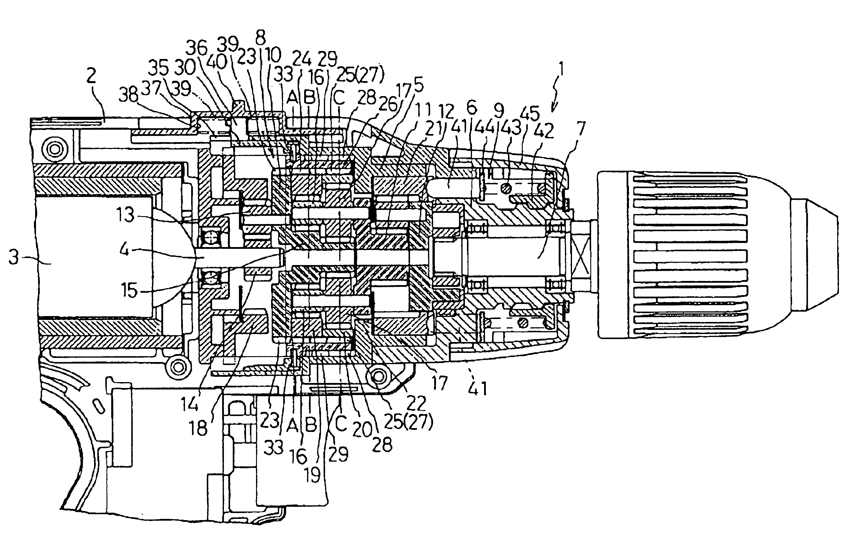
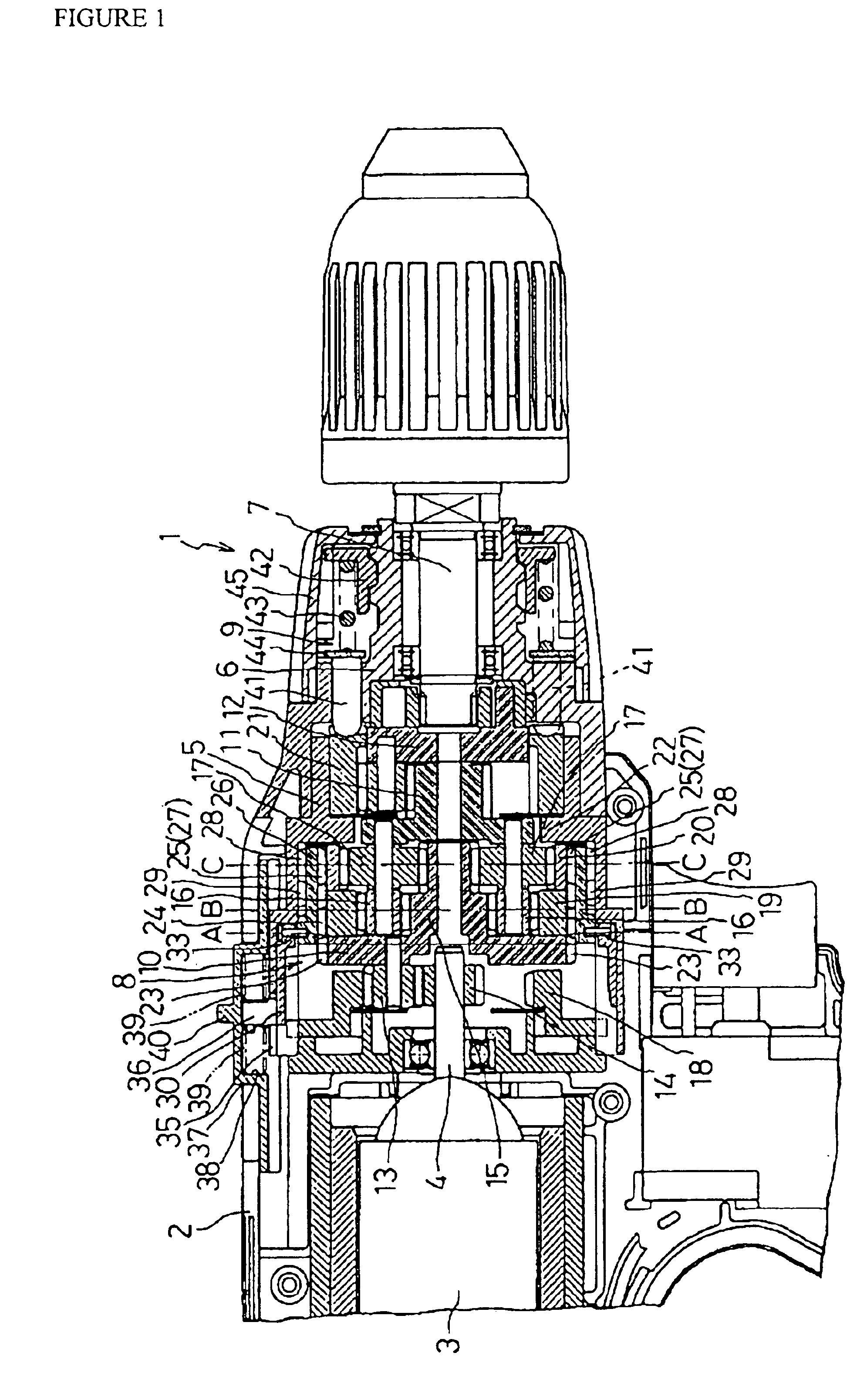
[0036]FIG. 1 is a partially cross-sectional side view of an essential part of a battery-powered driver-drill 1 constructed according to the teachings of the present invention. The driver-drill 1 includes a housing 2, a motor 3 with an output shaft 4 both encased in the housing 3, a first gear case 5 having a multiple-stepped cylindrical shape provided forward (to the right-hand side in the drawing) of the motor 3, and a second gear case 6 that is also provided forward of the motor 3 and rotatably supports a spindle 7 of the tool 1. The driver-drill 1 further includes a clutch assembly 9 mounted forward of the second gear case 6 and an epicycle reduction gear unit 8 within the first gear case 5 and the second gear case 6. The epicycle reduction gear unit 8 includes three axially arranged stages of first, second, and third carriers 10, 11, and 12, respectively, each supporting three or four planetary gears on its rear face. Planetary gears 13 associated with the first carrier 10 revol...

embodiment 2

[0053]An alternate structure of the present invention is described hereinafter with reference to the attached drawings, in which identical or similar reference numerals or characters denote identical or similar parts or elements throughout the several views. Therefore, description of such elements is omitted in the following description.

[0054]FIG. 6 is a partially cross-sectional side view of an essential part of a battery-powered driver-drill 1a constructed according to the teachings of the present invention. As in the first embodiment, the driver-drill 1a includes the second carrier 11 with the small diameter gears 16 and the large diameter gears 17 within the epicycle reduction gear unit 8. However, the second and third internal gears 19 and 20 include on their outer peripheral surfaces teeth 50 and 51, respectively, that are sufficiently spaced apart to receive an engagement element, such as a pin 52, therebetween. Additionally, as shown in FIG. 7, a switchover ring 53 is rotata...


PUM


Abstract

A battery-operated driver-drill (1) includes an epicycle reduction gear unit (8) which encases a switchover sleeve (26) having inner teeth (27) and outer teeth (28). The gear unit (8) is rotatably mounted on second and third internal gears (19, 20) and integrally slidably connected with a slide plate (37). By operating the slide plate (37), the switchover sleeve (26) may be slid between a first position, in which the slide plate (37) engages one of the second and third internal gears (19, 20) while engaging axial ridges (29) of a first gear case (5), and a second position, in which the slide plate (37) simultaneously engages both the second internal gear (19) and a first carrier (10) adjacent to the second internal gear (19) while disengaged from the axial ridges (2).

Description

RELATED APPLICATION[0001]This application claims priority on Japanese Patent Application No. 2003-31542 filed on Feb. 7, 2003.BACKGROUND OF THE INVENTION[0002]1. Field of the Invention[0003]The present invention generally relates to electric power tools. More particularly, the present invention relates to an electric power tool, such as an electric screwdriver or driver-drill, employing an epicycle reduction gear unit to provide three-speed transmission for the spindle.[0004]2. Description of the Related Art[0005]A known type of electric screwdriver includes a housing, a motor, and an epicycle reduction gear unit with a plurality of axially arranged stages each including an internal gear, a plurality of planetary gears revolving on the internal gear, and a carrier supporting the planetary gears. Attached to the front end of the housing in this known tool is a spindle to which the rotation of the motor is transmittable via the reduction gear unit, which also reduces the speed of the ...

Claims


Application Information

Patent Timeline
Patent Type & Authority Patents(United States)
IPC IPC(8): B25F5/00B25B21/00
CPCB25F5/001B25B23/141
Inventor HARA, AKIHITOABE, HIDEKI
Owner MAKITA CORP
Why Eureka
Try Eureka