Hermetically sealed coin cell

Active Publication Date: 2006-01-10
WILSON GREATBATCH LTD
View PDF15 Cites 11 Cited by
  • Summary
  • Abstract
  • Description
  • Claims
  • Application Information

AI Technical Summary

Benefits of technology

[0007]The present invention coin cell is distinguishable from those of the prior art in that the opposite polarity terminals are isolated from one another using a glass-to-metal seal. Glassing a conductive disc inside a ring of greater diameter and height forms this seal. The height of the ring is equival

Problems solved by technology

However, as cell size becomes smaller, it becomes increasingly more complicated to perform the required welding and fabrication processes.
The problem with coin cells is, however, that the insulat

Method used


Image

  • Hermetically sealed coin cell
  • Hermetically sealed coin cell
  • Hermetically sealed coin cell

Examples


Embodiment Construction

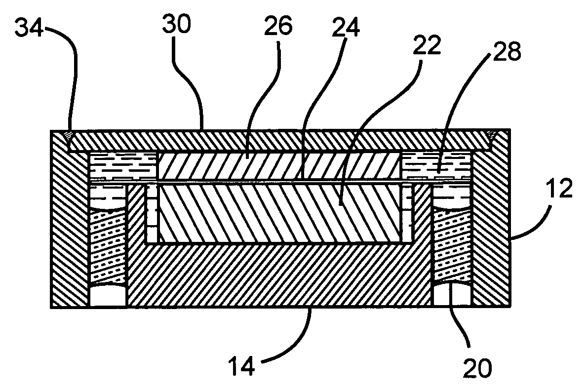
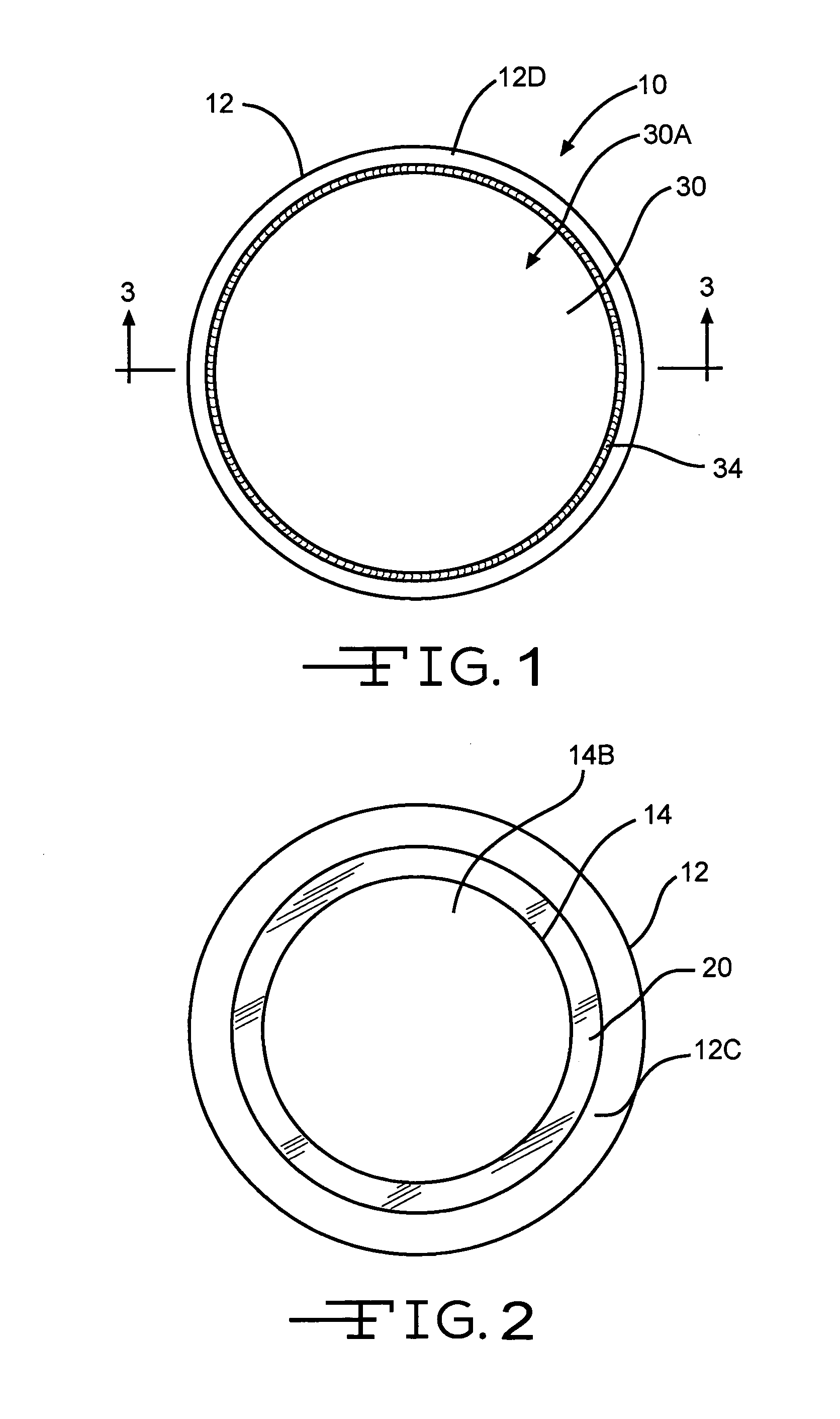
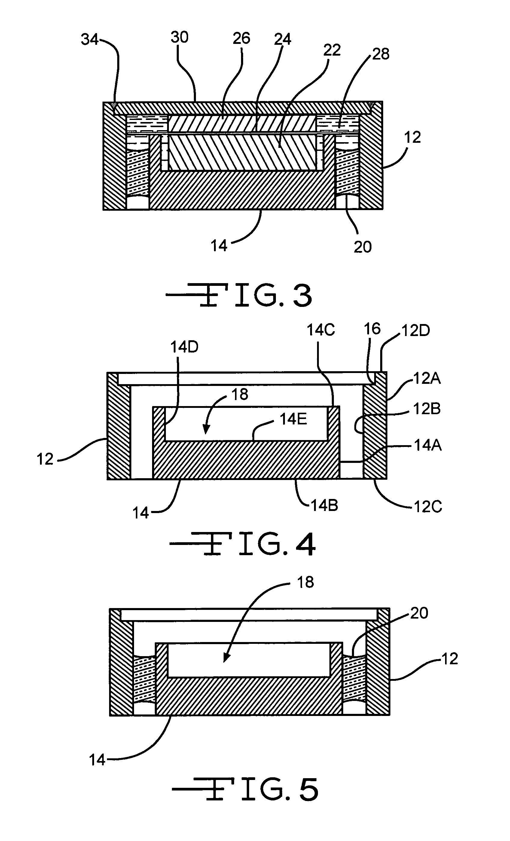
[0020]Referring now to the drawings, FIGS. 1 to 9 show a coin cell 10 according to the present invention. The coin cell 10 comprises a cylindrically shaped ring 12 surrounding a circular disc 14. The ring 12 has a cylindrical outer wall 12A that is coaxial with a cylindrical inner wall 12B. The outer and inner walls 12A, 12B of the ring 12 extend to and meet with a spaced apart and perpendicularly oriented bottom or lower end 12C and a top or upper end 12D. The upper end 12D includes an annular step 16 adjacent to the inner wall 12B.

[0021]The disc 14 serves as a base for one of the electrodes and comprises a cylindrically shaped outer wall 14A extending to a perpendicularly oriented bottom or lower end 14B and a top or upper end 14C. A circular recess 18 is provided in the disc. The recess 18 comprises a cylindrical inner wall 14D extending to an inner bottom wall 14E. The disc lower end 14B and the inner lower wall 14E are parallel to each other. Further, the outer and inner cylind...


PUM

PropertyMeasurementUnit
Pressureaaaaaaaaaa

Abstract

A hermetically sealed coin cell is described. The coin cell has the opposite polarity terminals isolated from one another by a glass-to-metal seal. Glassing a conductive disc inside a ring of greater diameter and height forms this seal. The height of the ring is equivalent to the desired height of the cell. The disc acts as one cell terminal, which can be positive or negative, and the ring serves as the other terminal. In plan view, both terminals are on the same side of the cell. This allows for easy mounting and connection to an electric circuit board, and the like.

Description

CROSS-REFERENCE TO RELATED APPLICATION[0001]The present application claims priority from U.S. provisional application Ser. No. 60 / 441,015, filed Jan. 17, 2003.BACKGROUND OF THE INVENTION[0002]1. Field of the Invention[0003]The present invention generally relates to the conversion of chemical energy to electrical energy. More particularly, the present invention relates to a hermetically sealed coin-type cell. The cell is of either a primary or a secondary chemistry.[0004]2. Prior Art[0005]Implantable electrochemical cells are in widespread use. These cells are hermetically sealed using an insulating glass to separate the terminal pin from the case. Power sources of this type prevent internal components, such as the electrolyte, from coming into contact with body tissue or sensitive electrical components of the associated implantable medical device. These cells are easily manufactured in large sizes. However, as cell size becomes smaller, it becomes increasingly more complicated to pe...

Claims


Application Information

Patent Timeline
IPC IPC(8): H01M2/08H01M2/02H01M2/04H01M2/06H01M4/58H01M6/16H01M10/40
CPCH01M2/023H01M2/0426H01M2/08H01M2/065Y10T29/49114Y10T29/4911Y02E60/10H01M50/56H01M50/169H01M50/186H01M50/191Y02P70/50
Inventor RUBINO, ROBERT S.GAN, HONGPRINZBACH, JOSEPHTAKEUCHI, ESTHER S.
Owner WILSON GREATBATCH LTD
Why Eureka
Try Eureka