Reticle barrier system for extreme ultra-violet lithography

a technology of ultra-violet lithography and barrier system, applied in the field of lithography, can solve the problems of affecting the quality of lithography, and affecting the quality of lithography, and achieve the effect of reducing the number of contaminants

Inactive Publication Date: 2006-01-10
ASML HLDG NV
View PDF1 Cites 8 Cited by
  • Summary
  • Abstract
  • Description
  • Claims
  • Application Information

AI Technical Summary

Benefits of technology

[0016]The present invention is directed to a reticle barrier system that prevents contaminants from landing on a mask within lithographic systems using extreme ultra violet light. In particular, a reticle barrier system is provided that consists of a mask barrier and a set of contact barriers. The mask barrier surrounds a mask formed on a reticle, while the contact barriers are affixed between the mask and contact spots on a reticle. The barriers have a height relative to the mask, and different geometries are provided. Collectively, the mask and contact barriers reduce the number of contaminants landing on a mask surface without the use of a pellicle. In an alternate embodiment, the reticle barrier system includes only a mask barrier. Similarly, in another alternate embodiment, the reticle barrier system includes only barriers around contact spots.
[0017]There are numerous benefits associated with the use of a reticle barrier system. First, the reticle barrier system significantly reduces the number of contaminants landing on the surface of a mask, and therefore the quality of wafers produced in an EUV lithographic system can be greatly enhanced. Second, unlike pellicles a reticle barrier system can be used in EUV lithographic systems.

Problems solved by technology

Airborne particles and dust that settle on the reticle can cause defects on the wafer.
Small image distortions or displacements in the reticle plane can swamp critical dimension and create overlay errors.
Particles that settle on the reticle can produce image distortion and / or defects.
Removal of particles from the reticle can cause damage to the reticle because such removal may involve direct contact with the reticle.
The pellicle approach, however, is not well suited for use in extreme-ultraviolet (EUV) applications.
Currently, there are no materials sufficiently transparent to EUV that can be used to make a pellicle.
In the absence of a pellicle, contaminants will land on the surface of the mask and degrade the quality of the wafers produced in EUV applications.
Nonetheless, airborne and inside-vacuum contaminants exist that can adhere to a mask.
In particular, contact spots on a reticle used to hold the reticle for transportation and placement within the lithographic device generate small contaminants or debris that can land on a mask.

Method used


Image

  • Reticle barrier system for extreme ultra-violet lithography
  • Reticle barrier system for extreme ultra-violet lithography
  • Reticle barrier system for extreme ultra-violet lithography

Examples


Embodiment Construction

[0031]While the present invention is described herein with reference to illustrative embodiments for particular applications, it should be understood that the invention is not limited thereto. Those skilled in the art with access to the teachings provided herein will recognize additional modifications, applications, and embodiments within the scope thereof and additional fields in which the invention would be of significant utility.

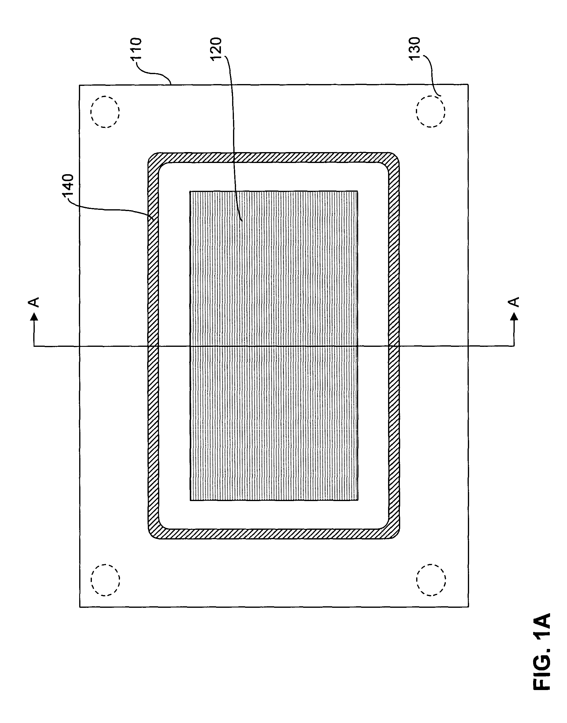
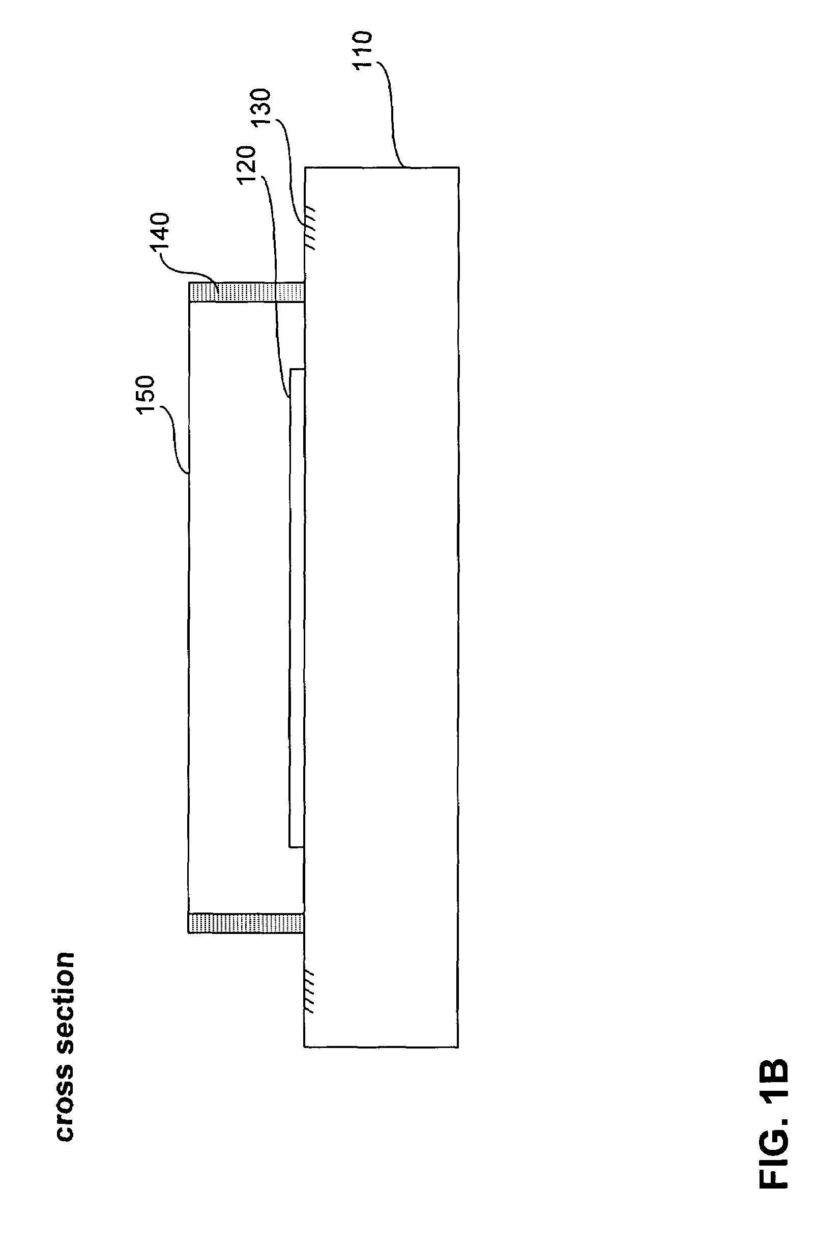
[0032]FIG. 1A provides a diagram of a lithographic reticle having a mask with a pellicle. Such an arrangement is commonly used in lithogrpahic applications other than those involving extreme ultraviolet (EUV). The system includes reticle 110; mask 120; contact spots, such as contact spot 130; and pellicle frame 140. In addition, as illustrated in FIG. 1B, which is a cross sectional view of the system depicted in FIG. 1A, the system also includes pellicle 150. As discussed above, pellicle 150 prevents contaminants from landing on the surface of mask 120. P...


PUM

PropertyMeasurementUnit
angleaaaaaaaaaa
thickaaaaaaaaaa
heightaaaaaaaaaa

Abstract

The present invention is directed to a reticle barrier system that prevents contaminants from landing on a mask within lithographic systems using extreme ultra violet light. In particular, a reticle barrier system is provided that consists of a mask barrier and a set of contact barriers. The mask barrier surrounds a mask formed on a reticle, while the contact barriers are affixed between the mask and contact spots on a reticle. The barriers have a height relative to the mask, and different geometries are provided. Collectively, the mask and contact barriers reduce the number of contaminants landing on a mask surface without the use of a pellicle. In an alternate embodiment, the reticle barrier system includes only a mask barrier. Similarly, in another alternate embodiment, the reticle barrier system includes only contact barriers.

Description

BACKGROUND OF THE INVENTION[0001]1. Field of the Invention[0002]The present invention relates to lithography, and more particularly, to reticle barrier systems used in lithography.[0003]2. Background of Invention[0004]Lithography is a process used to create features on the surface of substrates. Such substrates can include those used in the manufacture of flat panel displays, circuit boards, various integrated circuits, and the like. A semiconductor wafer; for example, can be used as a substrate to fabricate an integrated circuit.[0005]During lithography, a reticle is used to transfer a desired pattern onto a substrate. The reticle is formed of a material transparent to the lithographic wavelength being used, for example glass in the case of visible light. The reticle has an image printed on it. The size of the reticle is chosen for the specific system in which it is used. A reticle six inches by six inches and one-quarter inch thick may be used, for example. During lithography, a w...

Claims


Application Information

Patent Timeline
Patent Type & Authority Patents(United States)
IPC IPC(8): G03F9/00A47G1/12G03F1/14B44F1/00H01L21/027
CPCB82Y10/00G03F1/62G03F1/24B82Y40/00
Inventor ROUX, STEPHENLENOX, RICHARD
Owner ASML HLDG NV
Why Eureka
Try Eureka