Temperature adjusting system and exposure apparatus incorporating the same

Inactive Publication Date: 2006-01-17
CANON KK
View PDF12 Cites 18 Cited by
  • Summary
  • Abstract
  • Description
  • Claims
  • Application Information

AI Technical Summary

Benefits of technology

[0011]The present invention has been made in view of the above problems, and has as its object to provide

Problems solved by technology

As the energy of an F2 laser beam is absorbed by the moisture or oxygen contained in the atmosphere, a conventional exposure apparatus cannot be applied as it is.
The conventional inert gas circulating system has the following problems in the case of periodical maintenance such as cleaning a wafer chuck arranged in the sealed space, or trouble such as a wafer lost.
(1) When the operator needs to access the sealed space, the interior of the sealed space

Method used


Image

  • Temperature adjusting system and exposure apparatus incorporating the same
  • Temperature adjusting system and exposure apparatus incorporating the same
  • Temperature adjusting system and exposure apparatus incorporating the same

Examples


example)

(Example)

[0032]In the preferred example of the present invention, a case will be described wherein the temperature adjusting system according to the preferred embodiment of the present invention is incorporated in an exposure apparatus.

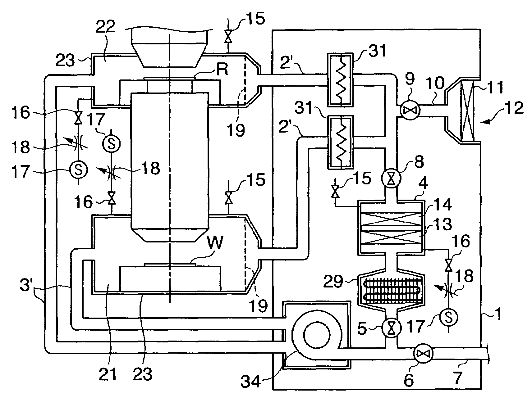
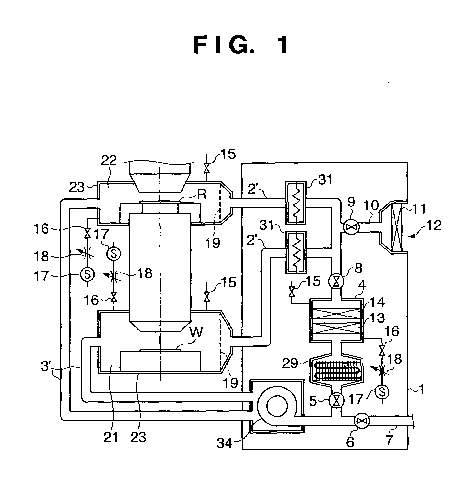
[0033]FIG. 1 is a conceptual view showing the arrangement of an exposure apparatus according to a preferred example of the present invention. In FIG. 1, the similar elements that are the same as those of the arrangement of the embodiment described above are denoted by the same reference numerals.

[0034]As shown in FIG. 1, a wafer space 21 where a substrate (wafer) W is arranged and a reticle space 22 where a master (reticle) R is arranged are surrounded by chambers 23. The wafer space 21 and reticle space 22 are spaces that can be sealed. A temperature adjustment system 1 has circulating paths 2′ and 3′ for circulating temperature-adjusted inert gas flows in the sealed spaces. More specifically, in the temperature adjustment system 1, temperature adjus...


PUM


Abstract

An apparatus including a chamber, a cooler, a circulating path, a first path, a second path, a first shut-off valve, and a second shut-off valve. The cooler cools an inert gas to be supplied to the chamber. The inert gas flows through the chamber and the cooler in the circulating path. The first path, connected to the circulating path at a first position downstream of an outlet port of the cooler and upstream of the chamber, introduces air to the circulating path. The second path, connected to the circulating path at a second position downstream of the chamber and upstream of an inlet port of the cooler, exhausts gas in the chamber. The first shut-off valve, arranged in the circulating path upstream of the first position and downstream of the outlet port of the cooler, closes before the introduction of the air. The second shut-off valve, arranged in the circulating path downstream of the second position and upstream of the inlet port of the cooler, closes, to prevent the air from flowing to the cooler.

Description

FIELD OF THE INVENTION[0001]The present invention relates to a temperature adjusting system and an exposure apparatus incorporating the same.BACKGROUND OF THE INVENTION[0002]The wavelength of an exposure light source used in the manufacture of semiconductors is becoming shorter as the pattern size shrinks. More specifically, the exposure light source has shifted from an i-line to an excimer laser, and its laser light source has also shifted from KrF to ArF. To establish a finer patterning technique, use of an F2 laser is under study.[0003]To construct an exposure system using an F2 laser as the light source, the problem of attenuation of the exposure light energy must be solved. As the energy of an F2 laser beam is absorbed by the moisture or oxygen contained in the atmosphere, a conventional exposure apparatus cannot be applied as it is.[0004]As a means for enabling adaptation to the F2 laser, a method of sealing a space where exposure light passes with a partition, or the like, an...

Claims


Application Information

Patent Timeline
IPC IPC(8): G03B27/42G03B27/52G03F7/20H01L21/00H01L21/027
CPCH01L21/67248H01L21/67109G03F7/70875F28D2021/0077
Inventor NOMOTO, MAKOTO
Owner CANON KK
Why Eureka
Try Eureka