Sensor head, luminance distribution measurement apparatus having the sensor head, and unevenness inspection/evaluation apparatus

a technology of luminance distribution and measurement apparatus, which is applied in the direction of optical radiation measurement, identification means, instruments, etc., can solve the problems of conventional sensor head measurement errors, inability to precisely measure this luminance characteristic, etc., and achieve the effect of measuring easily and quickly the luminance distribution of the entire pixels

Inactive Publication Date: 2006-01-17
JAPAN SCI & TECH CORP +1
View PDF10 Cites 10 Cited by
  • Summary
  • Abstract
  • Description
  • Claims
  • Application Information

AI Technical Summary

Benefits of technology

[0019]Luminance distribution measurement apparatuses of the invention may be equipped with the sensor heads adapted to measure easily and quickly the luminance distribution of the entire pixe...

Problems solved by technology

The above mentioned known luminance measurement apparatus have drawbacks in that they fail to measure this luminance characteristic precisely.
However, a conventional sensor head (e.g. a image sensing device 2, a CCD camera) suffers from measurement errors made by the image sensors at the opposite ends of the device looking at the pixel at large angles θ, as shown in FIG.
The errors will become larger when the LCD panel is moved for further measurement since the angle φ then increases.
Since such lens has only a limited dimension, it still suffers similar errors at large angle of incidence ...

Method used


Image

  • Sensor head, luminance distribution measurement apparatus having the sensor head, and unevenness inspection/evaluation apparatus
  • Sensor head, luminance distribution measurement apparatus having the sensor head, and unevenness inspection/evaluation apparatus
  • Sensor head, luminance distribution measurement apparatus having the sensor head, and unevenness inspection/evaluation apparatus

Examples


example 1

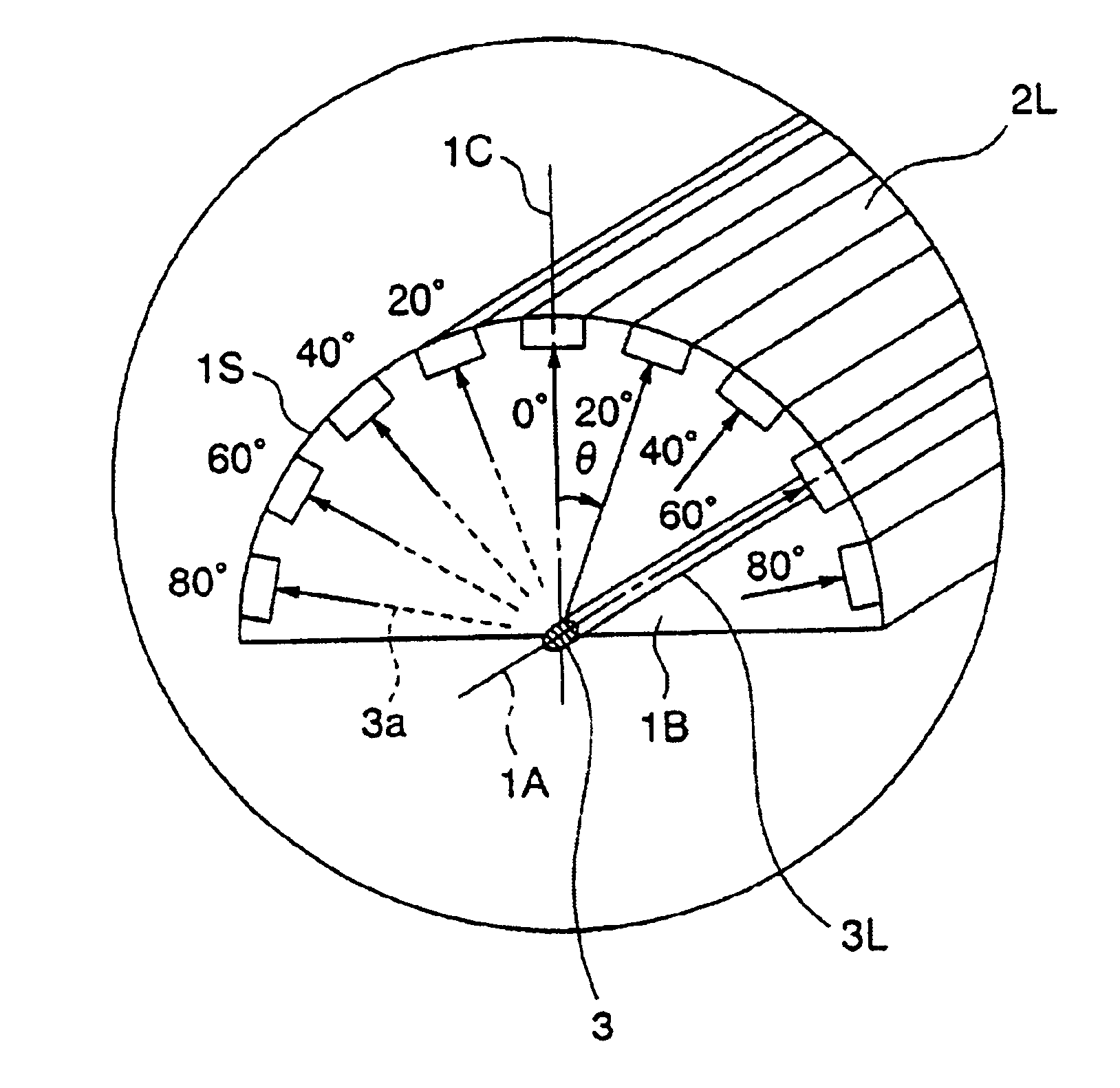
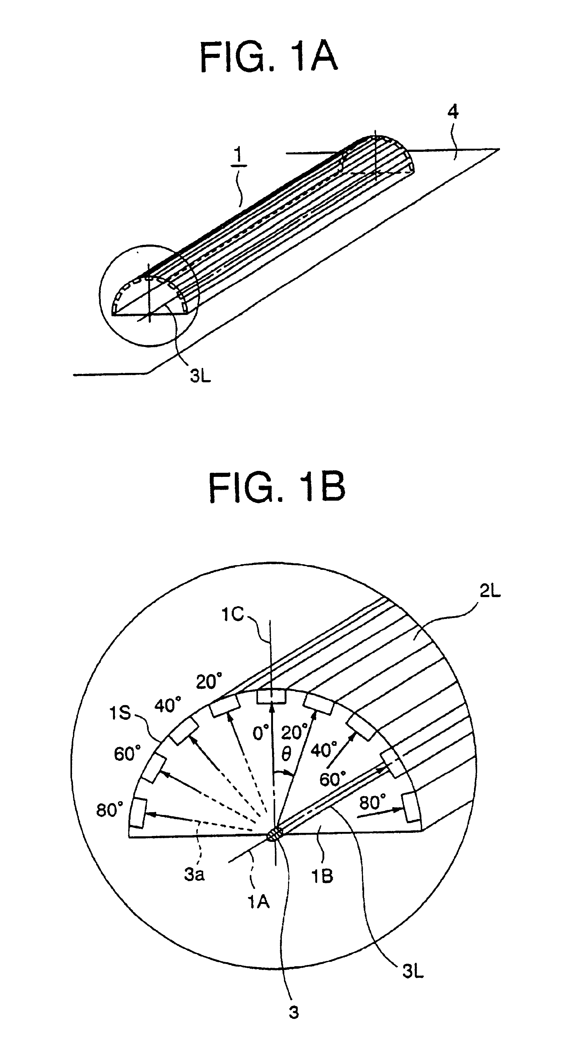
[0032]Referring now to FIGS. 1A and 1B, there is shown a sensor head having a multiplicity of linear image sensors according to the invention. Indicated generally by a reference numeral 2L in FIG. 2 are a multiplicity of linear image sensors. The area occupied by the pixels on the LCDs is a few times to 10 times as large as the area occupied by the linear image sensors. Each of the linear image sensors 2L extends in the direction of the axis 1A of imaginary semi-cylindrical surface 1S, and angularly spaced apart on the inner surface of the imaginary semi-cylinder with their light receiving face oriented towards the axis 1A. Thus, the normal of each light receiving face of the linear image sensor 2L passes through the axis 1A of the imaginary semi-cylinder. A sensor head 1 incorporating the linear image sensors 2L shown in FIGS. 1A and 1B has its axis 1A coincided with the line of pixels.

[0033]As shown in FIGS. 1A and 1B, the linear image sensors 2L are angularly disposed on the imag...

example 2

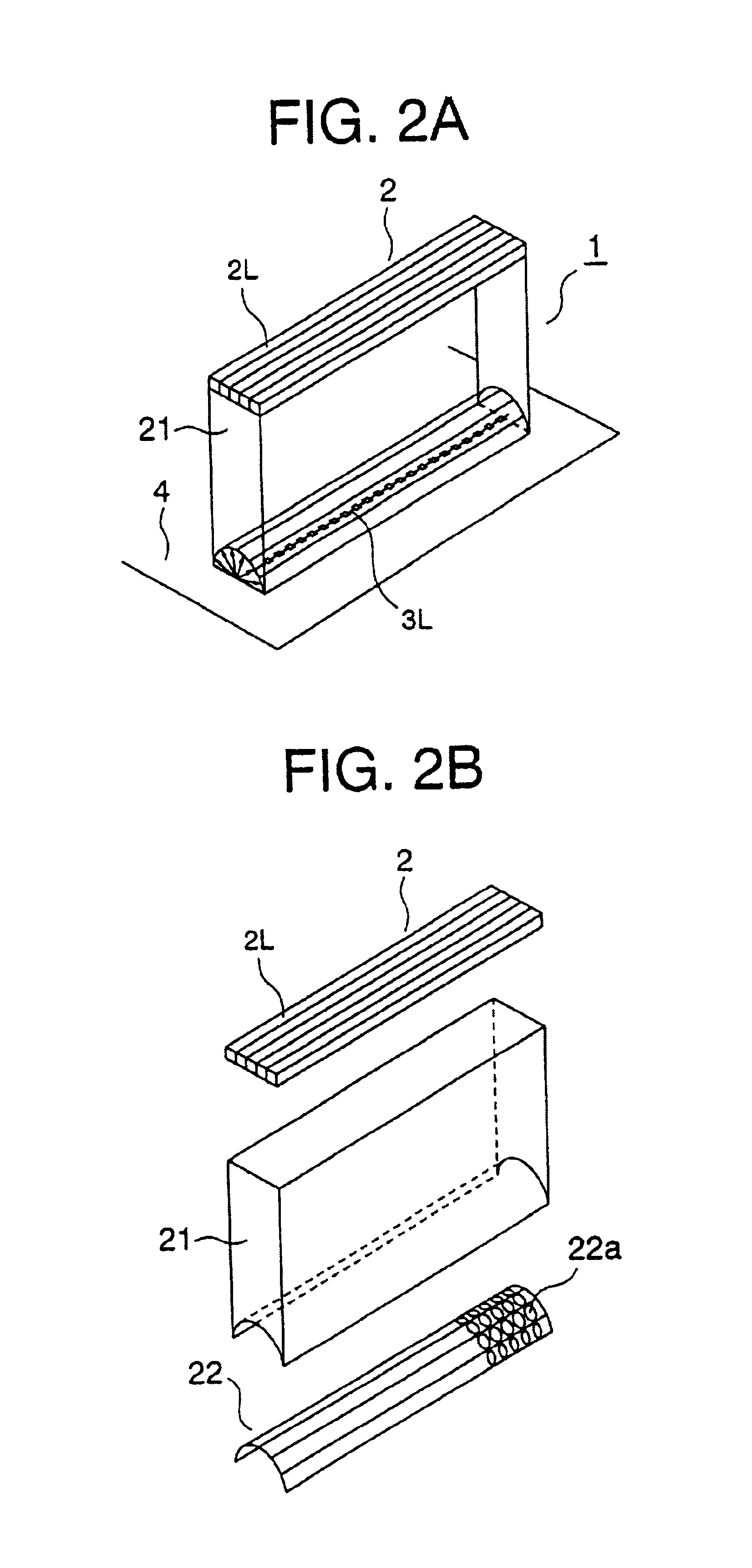
[0036]Referring to FIG. 2A, there is shown another embodiment of a sensor head that utilizes the linear image sensors of FIG. 1. This sensor head 1 includes a linear sensor assembly 2 having a multiplicity of linear image sensors 2L arranged on a common plane, and an optical system 21. In the example shown herein, each of the linear image sensors 2L is arranged in parallel with a given pixel line 3L. The optical system 21 is designed to receive beams of light that propagate from the pixel line 3L at different radial directions (i.e. at different vertical angles or angles of incidence) and for transmitting each beam to a corresponding linear image sensor 2L intended for sensing the light emitted from the pixel line 3L at a particular angle. The optical system 21 consists of such elements as for example a lens, a prism, a mirror, and a set of optical fibers. In the example shown in FIG. 2A, the light receiving faces of the optical system are disposed on the surface of an imaginary sem...

example 3

[0041]FIG. 3A shows an exemplary sensor head which utilizes a CCD area image sensor 2A instead of linear image sensors 2L shown in FIG. 3A. The optical system 21 is adapted to receive light radiated from a line of pixels and / or multiple lines of pixels 3L at different vertical angles and transmits the light to corresponding linear image sensors 2L. The light receiving faces can be distributed on an imaginary semi-cylinder for example. Each of the angular components of the radiated light is related to a corresponding sensing pixel of the area image sensor 2A by means of an optical element of the optical system 21, in the same manner as in the second example.

[0042]When the pixels in the pixel line 3L are activated, they emit beams of light at different vertical directions, which are picked up by the area image sensor 2A through the optical elements associated with the respective directions. In the example shown in FIG. 3A, the area image sensor 2A scans the sensing pixels in the area ...


PUM


Abstract

A sensor head has a multiplicity of linear image sensors in correspondence with different radial directions of light emitted from a pixel in a pixel line of an LCD panel. The linear image sensors extends in the direction of the axis of an imaginary semi-cylinder. The linear image sensors have light receiving faces that are angularly spaced apart on an imaginary semi-cylinder, with their light receiving faces having normals passing through the axis of the imaginary semi-cylinder. Interposed in the space between the LCD pixel and the linear image sensors is an optical system having a multiplicity of light paths associated with respective angular components of the radiation emitted from the pixel line. Each of the light paths receives a predetermined angular component of light and transmits the light thus reveived to a corresponding one of the linear image sensors.

Description

FIELD OF THE INVENTION[0001]The invention relates to a sensor head for detecting an angular distribution of the intensity or luminance of light radiated from a self-luminescent object such as lamps, light emitting diode (LED) displays, electro-luminescence (EL) displays, plasma display panels (PDP), and liquid crystal display (LCD) panels illuminated from behind for selective transmission of light to display an image. The invention also relates to an apparatus equipped with such sensor head for measuring the luminance distribution of such luminary object as mentioned above. The invention further relates to an apparatus which utilizes such sensor head to analyze unevenness in luminance of an image to be displayed (hereinafter referred to simply as unevenness).BACKGROUND OF THE INVENTION[0002]In recent years, there have been developed apparatuses for inspecting unevenness in angular distribution of luminance of LCD display panels for example, utilizing a linear image sensor having cha...

Claims


Application Information

Patent Timeline
IPC IPC(8): G01B11/30G01N21/55H01L27/00G01B11/00G01J1/00G01N21/958G01J1/02G01J1/06G01M11/00G01N21/00G01N21/94G02F1/13G09F9/00
CPCG01J1/00
Inventor YAMAKAWA, NOBORUTAGUCHI, TOSHIHIRO
Owner JAPAN SCI & TECH CORP
Why Eureka
Try Eureka