Imaging stabilization apparatus and method for high-performance optical systems

Inactive Publication Date: 2006-01-24
ULTRATECH INT INC
View PDF10 Cites 0 Cited by
  • Summary
  • Abstract
  • Description
  • Claims
  • Application Information

AI Technical Summary

Benefits of technology

[0009]Accordingly, a first aspect of the invention is an apparatus for providing image stabilization for a high-performance optical system. The apparatus includes a heating element arranged on an upper surface of a housing of the optical system. The heating elements provide heat to one or more gas-filled spaces between lens elements of the optical system. An insulating layer is arranged over at least a portion of the housing and facilitates the heating of gas present within the one or more spaces. The heating is performed so as to create a stable thermal environment within the optical system, wherein the warmer air resides closest to the upper portion of the housing and the cooler air resides closest to the lower portion of the housing.
[0010]A second aspect of the invention is that as described immediately above and further including a gas manifold is arranged adjacent the lower surface of the housing. The gas manifold is used to flow gas around the lower surface in order to prevent heating of the lower surface. The gas manifold may also be adapted to flow gas around heat-generating elements in the lithography system to prevent heat from such elements from heating the lower portion of the housing of the optical system.
[0011]A third aspect of the invention is a method of stabilizing the imaging of a high-performance optical system having one or more gas-filled spaces that are subject to thermal instability. The method includes heating the optical system so that gas in the one or more gas-filled spaces is heated so as to maintain a temperature differential within the one or more gas-filled spaces to form a stable thermal environment within the gas-filled spaces. In an example embodiment, the heating is performed on an upper surface of the optical system to avoid convective thermal instability in the one or more gas-filled spaces.

Problems solved by technology

If not properly dissipated, such heat can cause a negative thermal gradient across the housing of the lens, wherein the top of the lens is cooler than the bottom of the lens.
This, in turn, can cause convective heat transfer within the lens, resulting in unstable air motion within the lens and thus variations in refractive index along the optical path.
This, in turn, can cause slight displacements in the image at the image plane, which can lead to alignment and / or stage positioning errors, which ultimately degrade the quality of the device being fabricated.

Method used


Image

  • Imaging stabilization apparatus and method for high-performance optical systems
  • Imaging stabilization apparatus and method for high-performance optical systems
  • Imaging stabilization apparatus and method for high-performance optical systems

Examples


Embodiment Construction

[0017]The present invention relates to apparatus and methods for providing image stabilization in high-performance imaging systems.

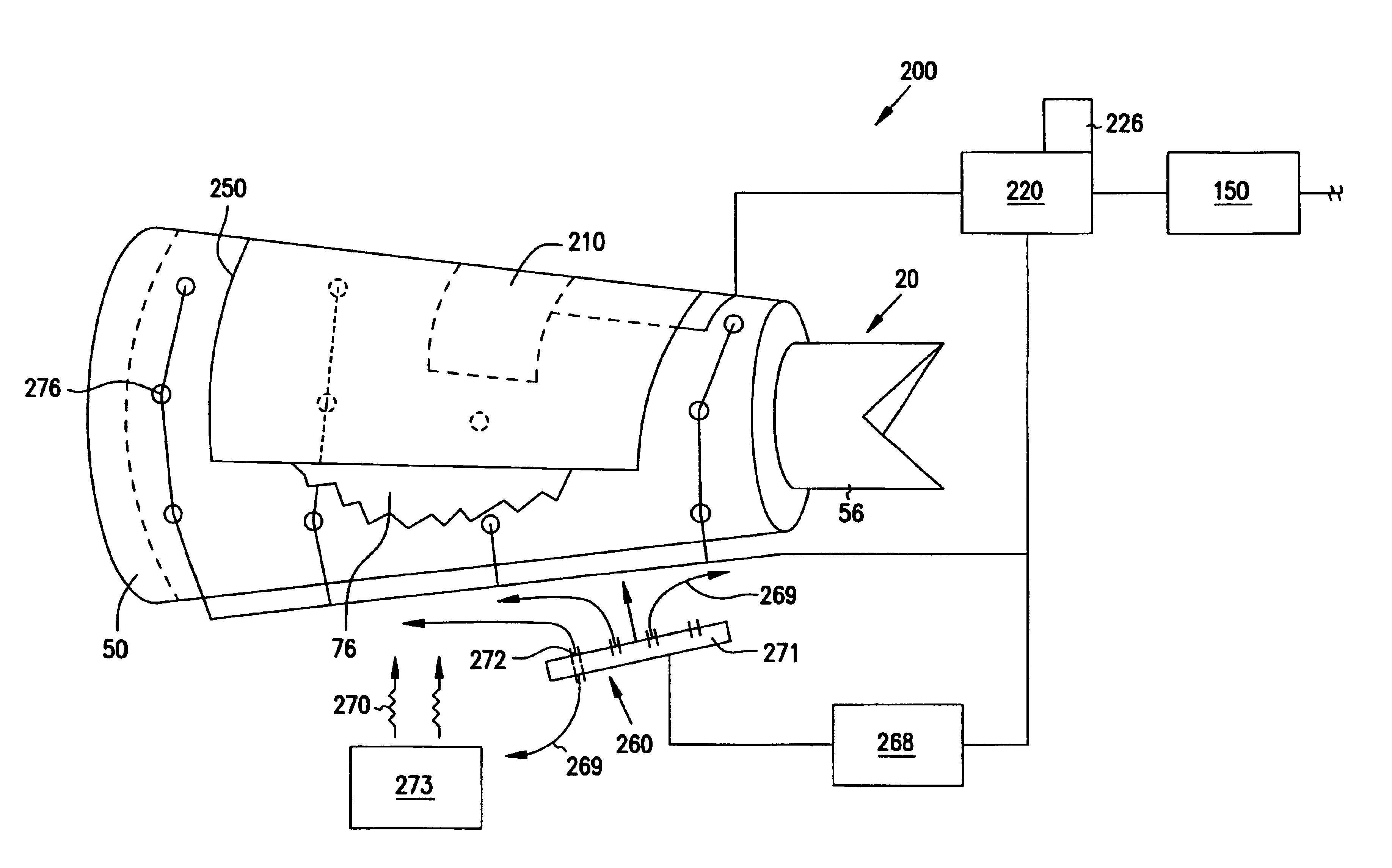
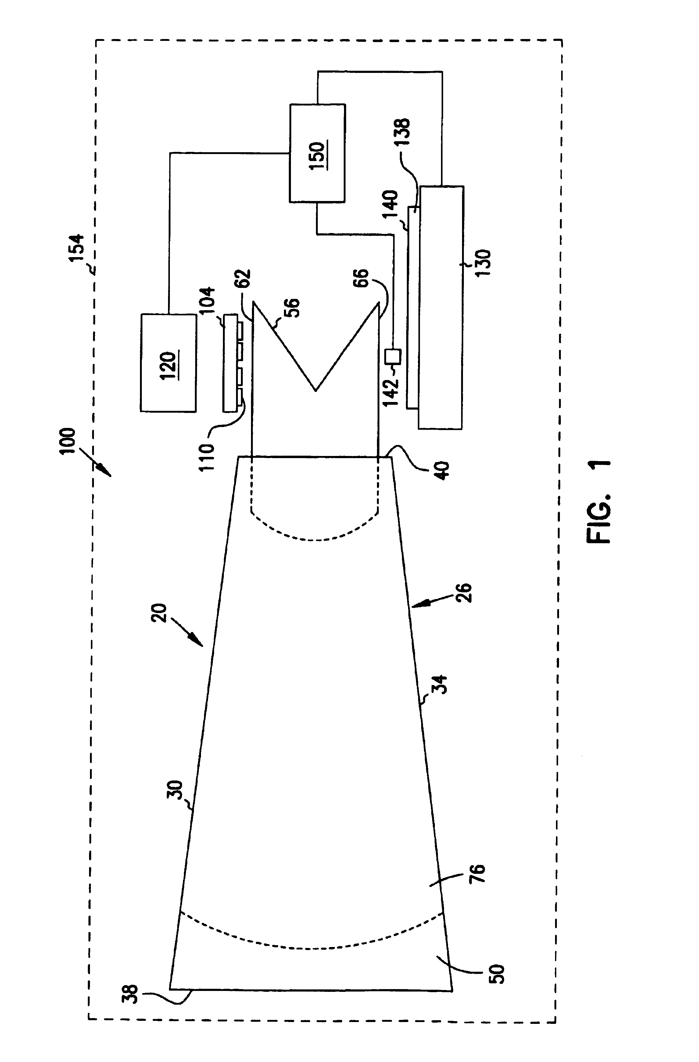
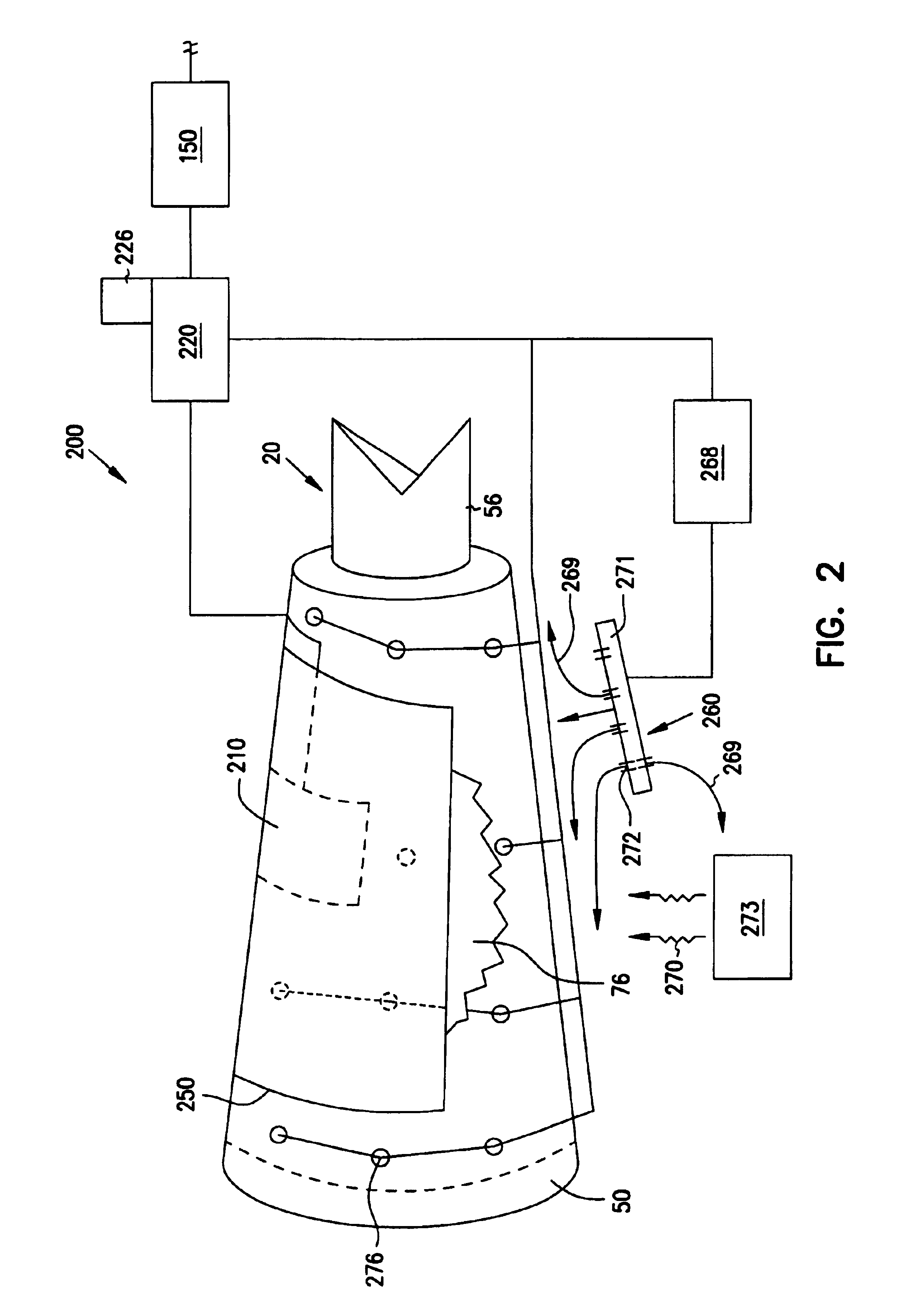
[0018]With reference to FIG. 1, there is shown an example high-performance optical system 20 in the form of a Wynne-Dyson type microlithographic lens. Optical system 20 includes a housing 26 with an upper surface 30, a lower surface 34 and first and second ends 38 and 40, respectively. Housing 26 supports a large concave mirror 50 at first end 38 and a refractive lens assembly 56 at second end 40. Lens assembly 56 includes an upper prism surface 62 and a lower prism surface 66. A gas-filled space 76 is defined by mirror 50, lens assembly 56 and housing 26. In practice, air or another gas (e.g., helium or nitrogen) is flowed through gas-filled space 76. Also in practice, optical system 20 can have one or more gas-filled spaces 76; only one is shown in FIG. 1 for ease of explanation.

[0019]Optical system 20 is shown as part of a lithography system 100 havin...


PUM


Abstract

An image stabilization apparatus and method for stabilizing the imaging of a high-performance optical system prone to imaging instabilities from thermal effects. Thermal instabilities within the lens, such as convection, can result in image placement errors in a high-performance optical system. The apparatus includes a heating element arranged on the upper surface of the optical system to provide heat to one or more gas-filled spaces in the optical system. An insulating blanket covers a portion of the optical system to uniformize the heating of the optical system and increase efficiency of the apparatus. The gas in the spaces is heated so that the warmer gases reside near the upper portion of the optical system, while the cooler gases reside near the lower portion of the optical system. This creates a stable thermal environment within the lens system, thereby stabilizing the imaging. Optionally gas can be flowed over the lower surface to keep heat from heating the lower portion of the optical system.

Description

CROSS REFERENCE[0001]This application is a Divisional Application of an earlier filed application by the same title having a filing date of Aug. 6, 2001 and a Ser. No. 09 / 923,734 which has issued as U.S. Pat. No. 6,617,555 on Sep. 9, 2003.BACKGROUND OF THE INVENTION[0002]1. Field of the Invention[0003]The present invention relates to apparatus and methods for providing image stabilization in high-performance optical systems.[0004]2. Description of the Prior Art[0005]Many optical systems used in manufacturing today are high-performance systems in which high-resolution images are formed. The images usually need to be imaged onto a light-sensitive medium, such as a photosensitive workpiece or a detector, with great precision.[0006]An example of a high-performance optical system is a microlithographic projection lens. Such lenses are used in lithography systems, which are used to fabricate semiconductor devices such as microcircuits. Microlithographic projection lenses typically are req...

Claims


Application Information

Patent Timeline
IPC IPC(8): H05B1/02G03F7/20
CPCG03F7/70891G03F7/70225
Inventor NEWCOMB, MICHAEL A.MAPOLES, EVAN R.GAINES, DAVID P.SHANNON, STEVE
Owner ULTRATECH INT INC
Why Eureka
Try Eureka