
Integrated power module with reduced thermal impedance

Inactive Publication Date: 2006-01-24
THE BOEING CO
View PDF5 Cites 30 Cited by
  • Summary
  • Abstract
  • Description
  • Claims
  • Application Information

AI Technical Summary

Benefits of technology

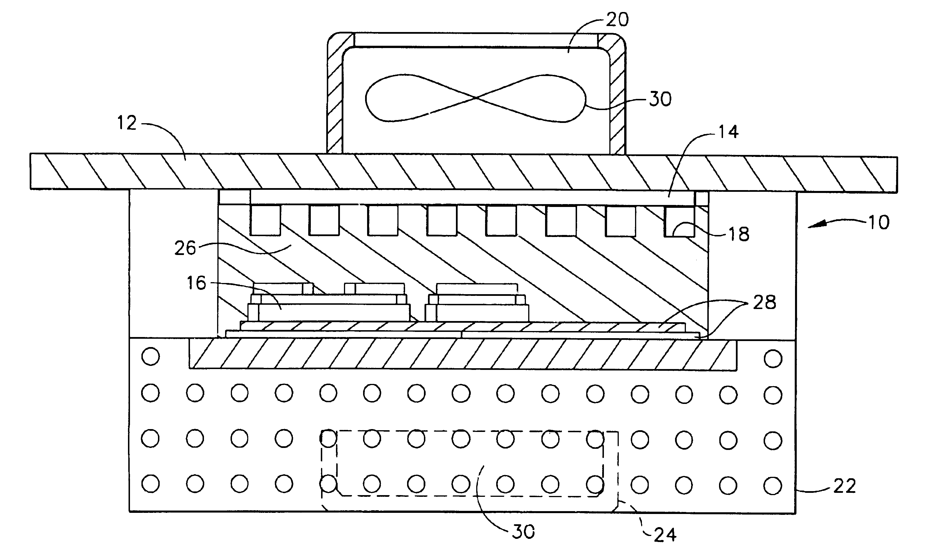
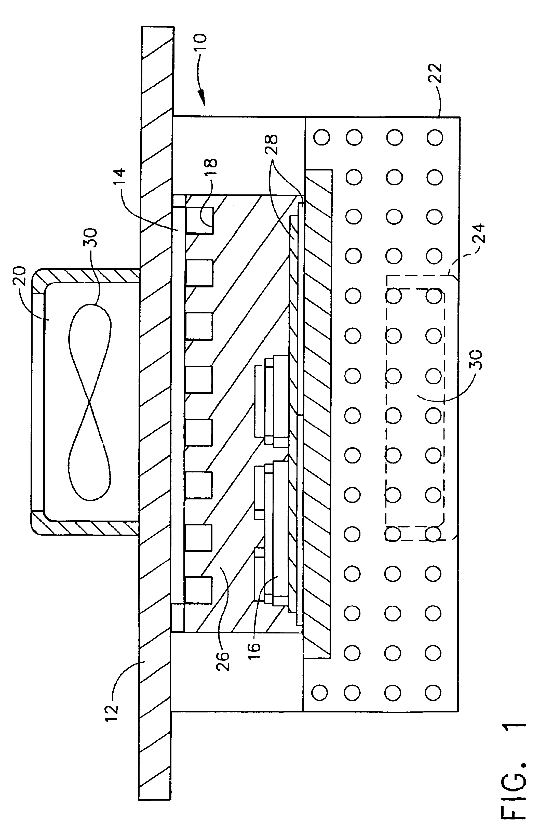
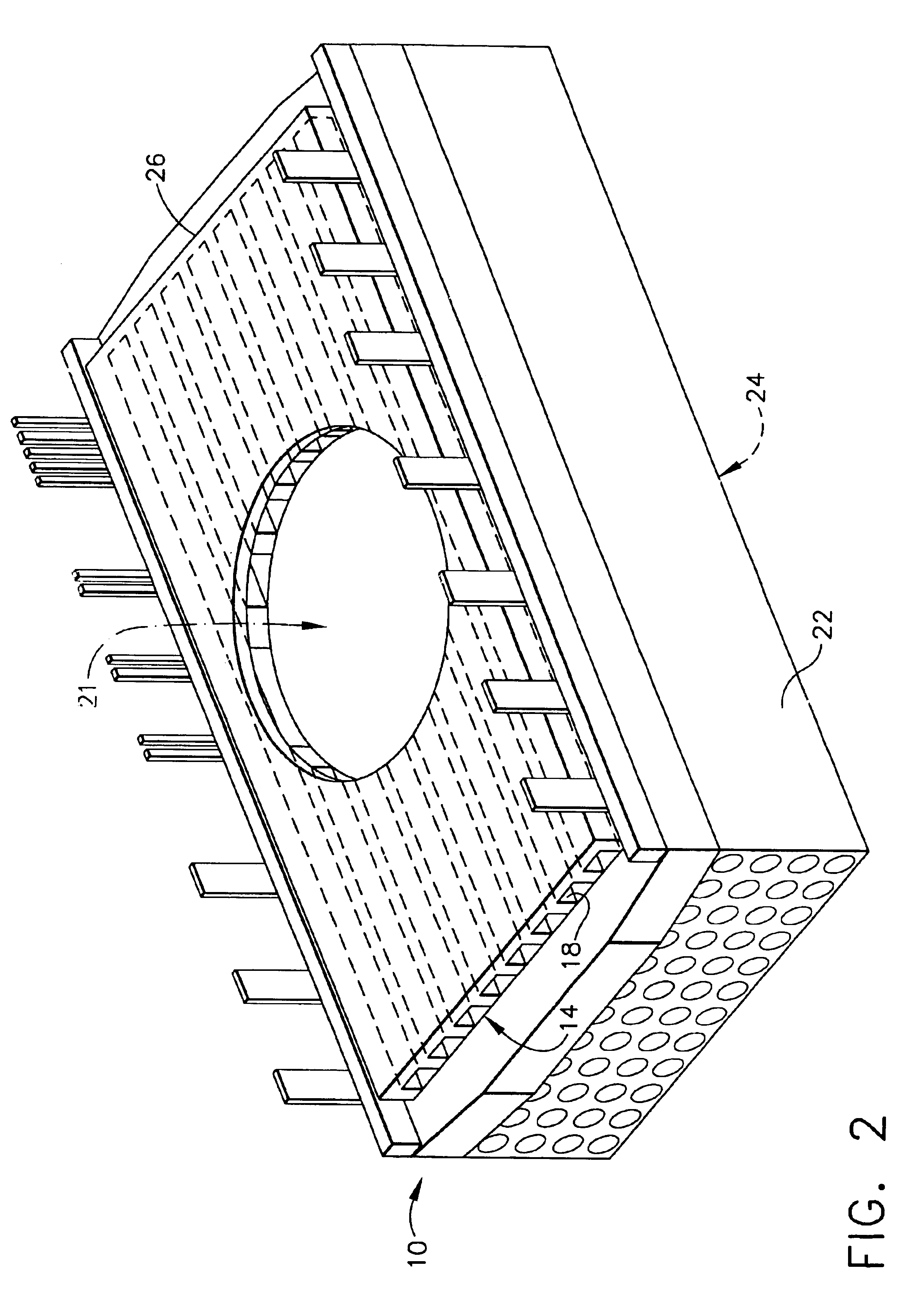
[0009]In yet another aspect of the invention there is disclosed a method for cooling an integrated power module containing a number of semiconductor power devices, and which includes dissipating heat and cooling the module by providing thermal interfaces on the opposed sides or the top and bottom surfaces of the module. The thermal impedance of a power semiconductor circuit and module is lowered by employing a new embedded thermal interface on the top side of a power module package, in addition to a compact bottom-side thermal interface provided via a base plate for increased cooling of the device, enabling elevated temperature operation.
[0010]Other aspects of the invention include having the top-side or front face thermal interface, for example a heat remover or exhaust fan, directly cool the internal power semiconductor dies, gate area of the switching devices, wire joints and bus joints, which are subject to heat flux concentration. A heat remover is employed adjacent the bottom face thermal interface to provide dual face cooling effective in reducing the inner thermal impedance between the power semiconductor devices and the external thermal interfaces. This feature in turn reduces the junction temperature rise of the power devices from their base plate / heat-sink temperature, thus allowing safer operation in elevated ambient temperatures and enabling a more compact package design and / or one of lower weight.

Problems solved by technology

However, a conventional power converter design is unable to achieve this operating temperature due to the built in thermal impedance of the power device or module and limited power device junction temperature.
These effects significantly increase total power loss, thus increasing thermal stress and cooling requirements for the power devices and decreasing the converter efficiency.
Such a dual-side thermal interface and cooling design reduces the weight and volume associated with conventional cooling mechanisms not employing a dual thermal interface and increases the ambient operating temperature limit of the power converter.

Method used


Image

  • Integrated power module with reduced thermal impedance
  • Integrated power module with reduced thermal impedance
  • Integrated power module with reduced thermal impedance

Examples


Embodiment Construction

[0017]The following detailed description is of the best currently contemplated modes of carrying out the invention. The description is not to be taken in a limiting sense, but is made merely for the purpose of illustrating the general principles of the invention, since the scope of the invention is best defined by the appended claims.

[0018]The present invention generally provides unique, dual-side, thermal interfaces on an integrated power module used on a commercially available IGBT power converter. The converter results in improved cooling of the module, which finds use, for example, in aircraft cooling systems and actuation systems. This is unlike the prior art in that dual-sided cooling of the module occurs with increased efficiency.

[0019]Referring now to the accompanying drawings (in which like reference numbers indicate like parts throughout several views), and more particularly, to FIG. 1, there is shown a cross-sectional view of a generic embodiment of a power module in acco...


PUM


Abstract

A dual-side thermal interface and cooling design of an integrated power module is disclosed which effectively reduces the equivalent thermal impedance on the power module by 20%. This in turn reduces the temperature rise of the junction temperature of the power devices inside the power module by 20% with an equivalent load current. As a consequence the weight and volume associated with the conventional cooling mechanism not employing a dual thermal interface is reduced, thus increasing the ambient operating temperature limit of a power converter in the module.

Description

BACKGROUND OF THE INVENTION[0001]This present invention generally relates to high-power-density power modules and, more specifically; to an electrically-powered, high-power-density power module useful as a power converter or inverter that can operate in an elevated temperature environment, with reduced weight and size, and increased reliability, which are critical for aircraft, space, military as well as many industrial applications.[0002]In a completely sealed vehicle compartment, such as found on electrical aircraft and spacecraft subsystems, the ambient temperature of the power converters can be over 90 degrees centigrade, which is often dictated by use of hydraulic fluid as the coolant. However, a conventional power converter design is unable to achieve this operating temperature due to the built in thermal impedance of the power device or module and limited power device junction temperature.[0003]IGBTs (Isolated Gate Bipolar Transistors) are popular power devices in use as puls...

Claims


Application Information

Patent Timeline
IPC IPC(8): H01L23/34H01L23/10H01L23/373H01L23/433H01L23/467
CPCH01L23/3735H01L23/4334H01L23/467H01L2924/3011H01L2924/0002H01L2924/00
Inventor CHANG, JIECHIU, STEPHENMORRIS, WINFRED
Owner THE BOEING CO
Learn More