Actuator driving device of working machine
a technology of working machine and driving device, which is applied in the direction of dynamo-electric converter control, multiple dynamo-motor starters, servomotors, etc., can solve the problems of high manufacturing cost, low manufacturing cost, and limited working space for devices, and achieves a large working area in the working machine, high thrust, and strict space-saving
- Summary
- Abstract
- Description
- Claims
- Application Information
AI Technical Summary
Benefits of technology
Problems solved by technology
Method used
Image
Examples
embodiment 1
[0029](a) Embodiment 1
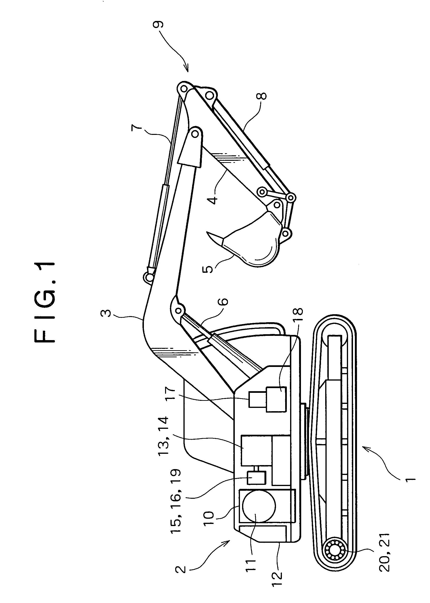
[0030]FIG. 1 shows the entire configuration of a hydraulic excavator. In the figure, on a crawler type lower traveling body 1 is rotatably mounted an upper traveling body 2. In front of the upper rotating body 2 is mounted an excavating attachment 9 which includes a boom 3, an arm 4, a bucket 5, a boom cylinder for boom rising / falling 6, an arm cylinder for arm operating 7, and a bucket cylinder for bucket operating 8.
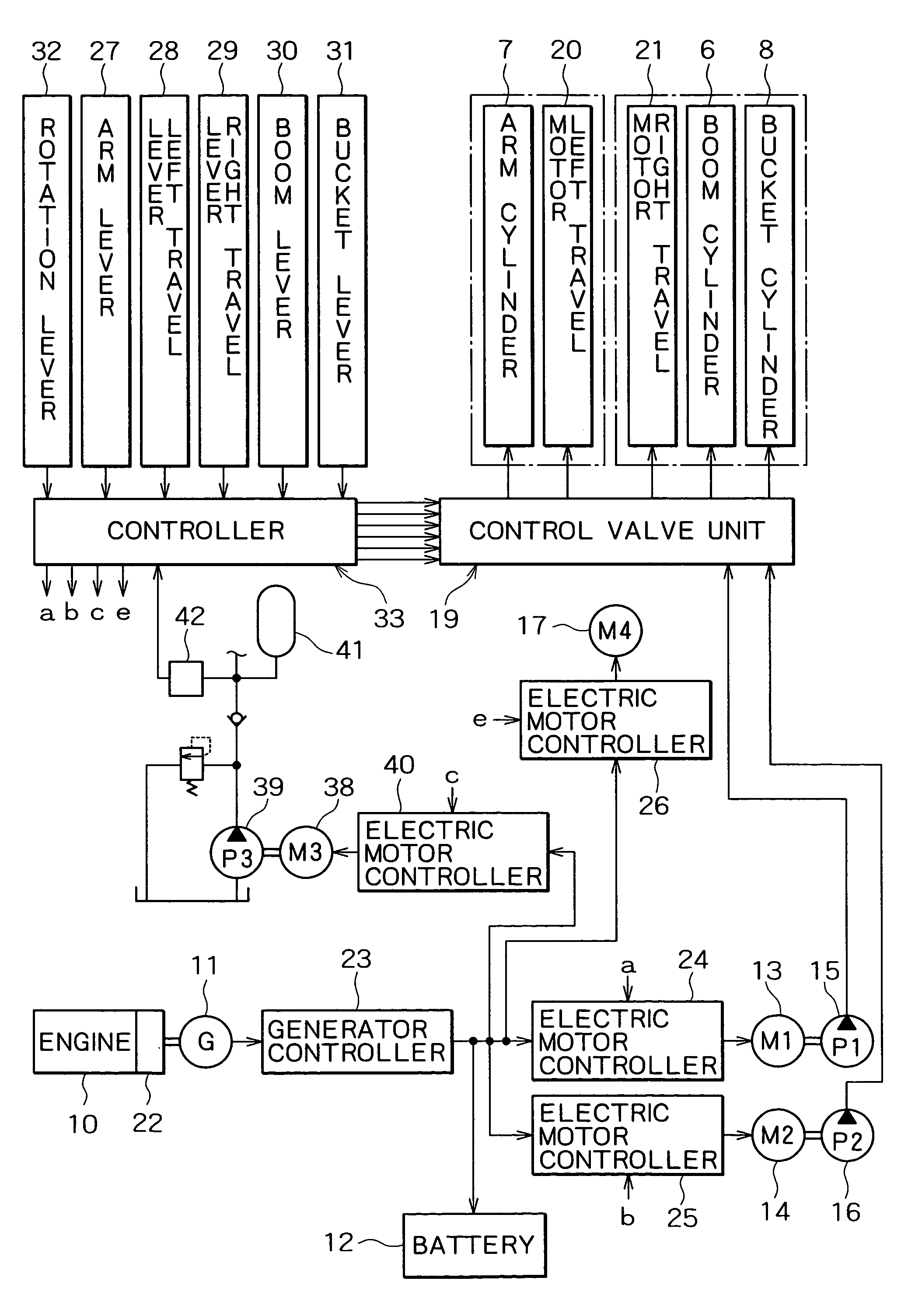
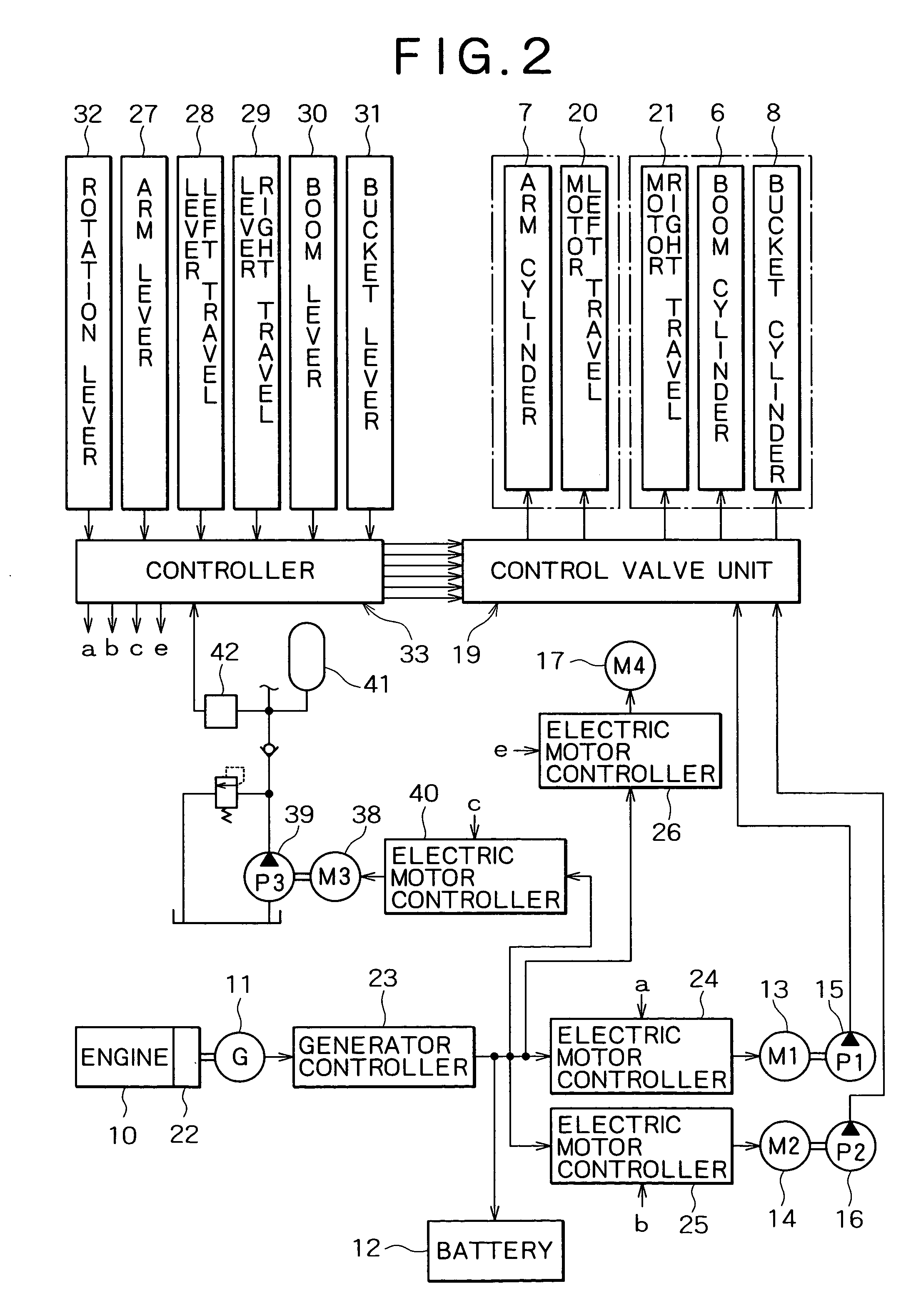
[0031]In the upper rotating body 2 are disposed an engine 10 as a power source, a power generator 11 driven by this engine 10, a battery 12, two electric motors, i.e., a first electric motor 13 and a second electric motor 14 (one of which is shown in the figure, and which are denoted at M1 and M2 in FIG. 2), and first and second hydraulic pumps 15 and 16 (one of which is shown in the figure, and which are denoted at P1 and P2) individually driven by both electric motors 13 and 14. Further, in the rotating body 2 are disposed an electric motor for ...
embodiment 2
[0058](b) Embodiment 2
[0059]FIG. 8 shows the configuration of driving and control systems of a hydraulic excavator according to the second embodiment of the invention. In the figure, elements that are in common to the first embodiment are given the same reference characters, and thus explanation thereof will be omitted.
[0060]As shown in FIG. 8, a generator-electric-motor 11a and first, second, and third hydraulic pumps 15, 16, and 39 (in the figure, which are denoted at P1, P2, and P3, respectively) are altogether connected to an output shaft of the engine 10. It is noted that a boom and a rotating element are individually driven. That is, a boom cylinder for boom riding / falling 6 is operated by pressure oil supplied from a hydraulic motor for the boom 46a (denoted at OM5) which is driven by an electric motor for the boom 44 (denoted at M5). This pressure oil is supplied from a hydraulic pump for the boom 46 (denoted at P5) driven by the boom electric motor 44. The controller 33 out...
embodiment 3
[0066](c) Embodiment 3
[0067]The third embodiment is constituted by replacing the pump of the first embodiment with a variable capacity type one. FIG. 10 shows electric motor and pump characteristics of a hydraulic excavator according to the third embodiment.
[0068]As shown in FIGS. 10A and 10B, the first and second electric motors 13 and 14 have the maximum power of 3000 min−1×70 Nm=22 kW as a predetermined rated output. The first and second hydraulic pumps 15 and 16 are controlled to have the following constant values: capacity q of 20 cm3 / rev; a maximum pressure of 30 MPa; and a torque of 70 Nm. The combination of the electric motor and the pump provides a graph indicating a relationship between pressure and flow rate, such as that shown in FIG. 11. By controlling the revolving speeds of the first and second electric motors 13 and 14 by an operator's manipulation, amount of discharge of the first and second pumps 15 and 16 is controlled.
[0069]The first and second hydraulic pumps 15...
PUM
 Abstract
Description
Claims
Application Information
 - R&D
- Intellectual Property
- Life Sciences
- Materials
- Tech Scout
- Unparalleled Data Quality
- Higher Quality Content
- 60% Fewer Hallucinations
Browse by: Latest US Patents, China's latest patents, Technical Efficacy Thesaurus, Application Domain, Technology Topic, Popular Technical Reports.
© 2025 PatSnap. All rights reserved.Legal|Privacy policy|Modern Slavery Act Transparency Statement|Sitemap|About US| Contact US: help@patsnap.com


