Engine generator

a generator and engine technology, applied in the direction of electric generator control, dynamo-electric converter control, instruments, etc., can solve the problems of engine generator, generator output circuit, generator starting circuit, etc., and achieve the effect of simple circuit configuration, easy control, and simple configuration

Inactive Publication Date: 2006-01-24
HONDA MOTOR CO LTD
View PDF5 Cites 27 Cited by
  • Summary
  • Abstract
  • Description
  • Claims
  • Application Information

AI Technical Summary

Benefits of technology

[0015]According to a first aspect of the present invention, a simple circuit configuration and easy control is realized because the generator output circuit and the electric motor starting circuit are not required separately to be provided and separate switching of wiring connection for operation as an electric motor and as a generator is not required.
[0016]And, according to a second aspect of the present invention, it is possible not to apply a high voltage from a DC—DC converter to an inverter. Accordingly, since a high withstand voltage is not required, only a cheap inverter with a simpl...

Problems solved by technology

But the high-voltage battery is expensive.
Moreover, the engine generator in which a generator output circuit and an electric motor starting circuit are separately provided has not met the demand for smaller size and reduction in the number of components.
Though the number of components can be reduced in the previous engine generator, in which the generator output circuit is also used as the electric motor...

Method used


Image

  • Engine generator
  • Engine generator
  • Engine generator

Examples


Embodiment Construction

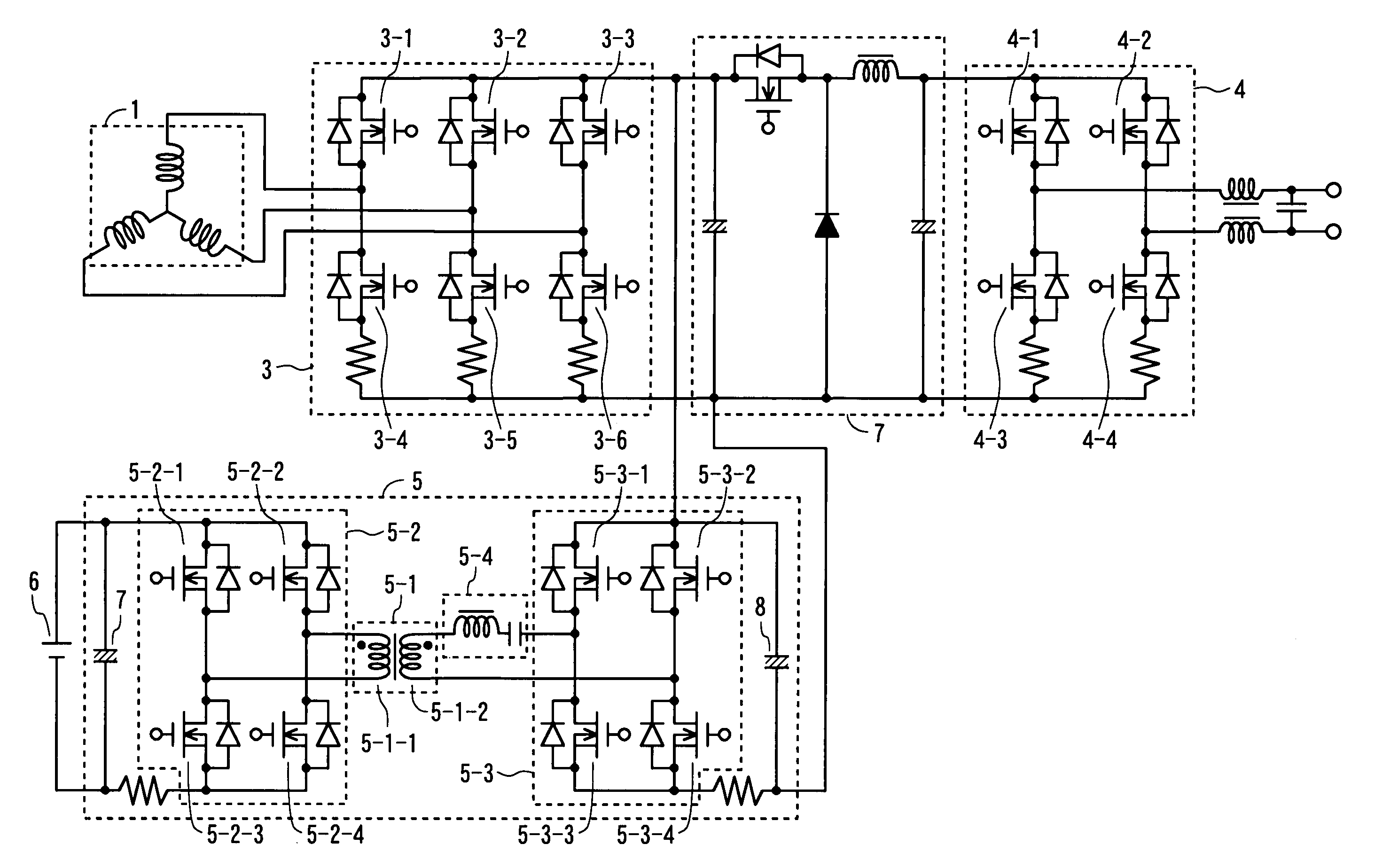
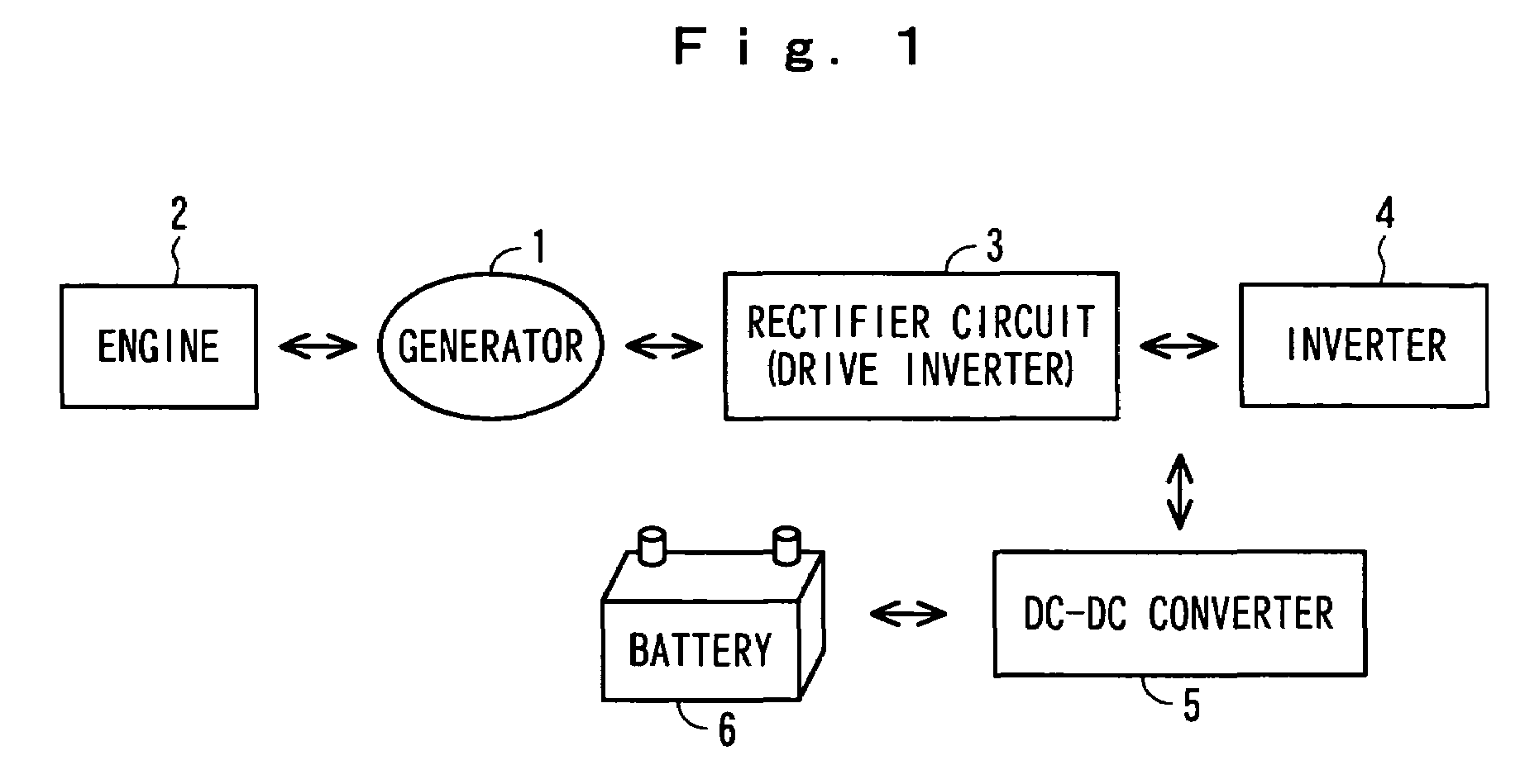
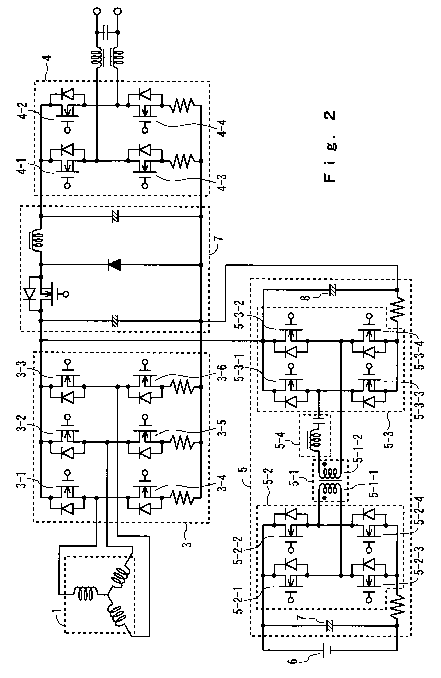
[0021]Hereinafter, the present invention will be explained in detail, referring to drawings. FIG. 1 is a block diagram showing a concept of an engine generator according to the present invention. In the drawing, a generator 1 is connected to an engine 2. The generator 1 comprises, for example, a three-phase multipolar magnet generator and is a dual-purpose generator both for a generator function and for an electric motor function, which can be also operated as an electric motor.

[0022]A rectifier circuit 3 comprising a bridged rectifying element rectifies the output of the generator 1. Moreover, switching elements such as field effect transistors (FETs) are connected in parallel with each rectifying element in the rectifier circuit 3. These switching elements form a drive inverter by which a DC voltage is converted into a three-phase AC voltage by ON-OFF control of the switching elements for application to the generator 1. Here, the rectifying elements forming the rectifier circuit 3...


PUM


Abstract

An engine generator, sufficiently meeting a demand for a simple configuration and easy control, is provided. The output of a generator 1 connected to an engine 2 is output through a rectifier circuit 3 and an inverter 4. The generator 1 is a dual-purpose generator both for a generator function and for an electric motor function, and is driven by a drive inverter as an engine starting electric motor. A DC—DC converter 5 is provided between the output side of the rectifier circuit 3 and the output terminal of a battery 6. The generator 1 is driven as an engine starting electric motor, using the battery 6 as a power supply, when the engine is started.

Description

BACKGROUND OF THE INVENTION[0001]1. Field of the Invention[0002]The invention relates to an engine generator, and more particularly, to an engine generator which uses a generator driven by an engine as an engine starting electric motor.[0003]2. Description of the Related Art[0004]An engine generator has diffused into widespread practice as a power supply device for various kinds of uses such as portable use and emergency one. In recent years, an engine generator has been also used as an engine starting electric motor, especially, responding to a demand for smaller size and reduction in the number of components.[0005]If the alternating current (AC) output of the engine generator is, for example, 100 V AC when an engine generator is also used as an engine starting electric motor, a direct current power supply (high voltage battery) of about 140 V is required to drive the generator as an engine starting electric motor, because an output of 140 V or more is required as a peak value of t...

Claims


Application Information

Patent Timeline
IPC IPC(8): H02P9/00F02N11/04F02N11/08H02J7/14H02M3/335H02P9/04
CPCB60L11/1811H02J7/1438H02M3/33584H02J7/1492B60L2210/10F02N11/04Y02T90/14Y02T10/7005Y02T10/7216Y02T90/127B60L53/20Y02T10/70Y02T10/7072Y02T10/72H02P9/04Y02T90/12
Inventor EGUCHI, HIROYUKISHIMIZU, MOTOHIRO
Owner HONDA MOTOR CO LTD
Why Eureka
Try Eureka