
Process and device for estimating the impulse response of an information transmission channel, in particular for a cellular mobile telephone

a technology of information transmission channel and impulse response, which is applied in the direction of channel estimation, transmission system, line-faulst/interference reduction, etc., can solve the problems of inter-symbol interference, interference between symbols, and performance of digital communication system

Inactive Publication Date: 2006-01-24
STMICROELECTRONICS SRL
View PDF24 Cites 40 Cited by
  • Summary
  • Abstract
  • Description
  • Claims
  • Application Information

AI Technical Summary

Benefits of technology

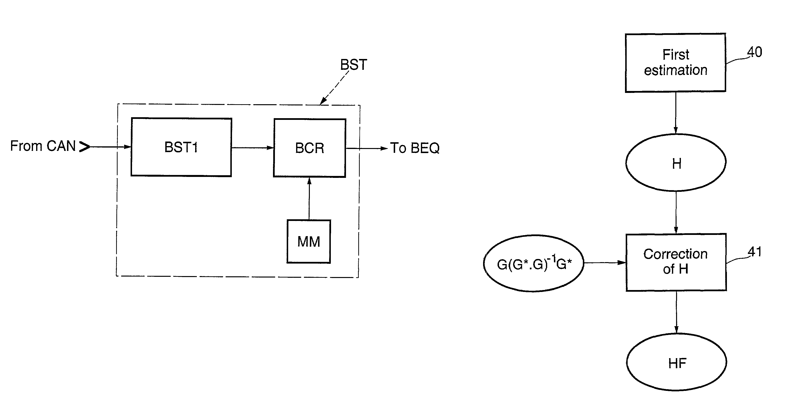
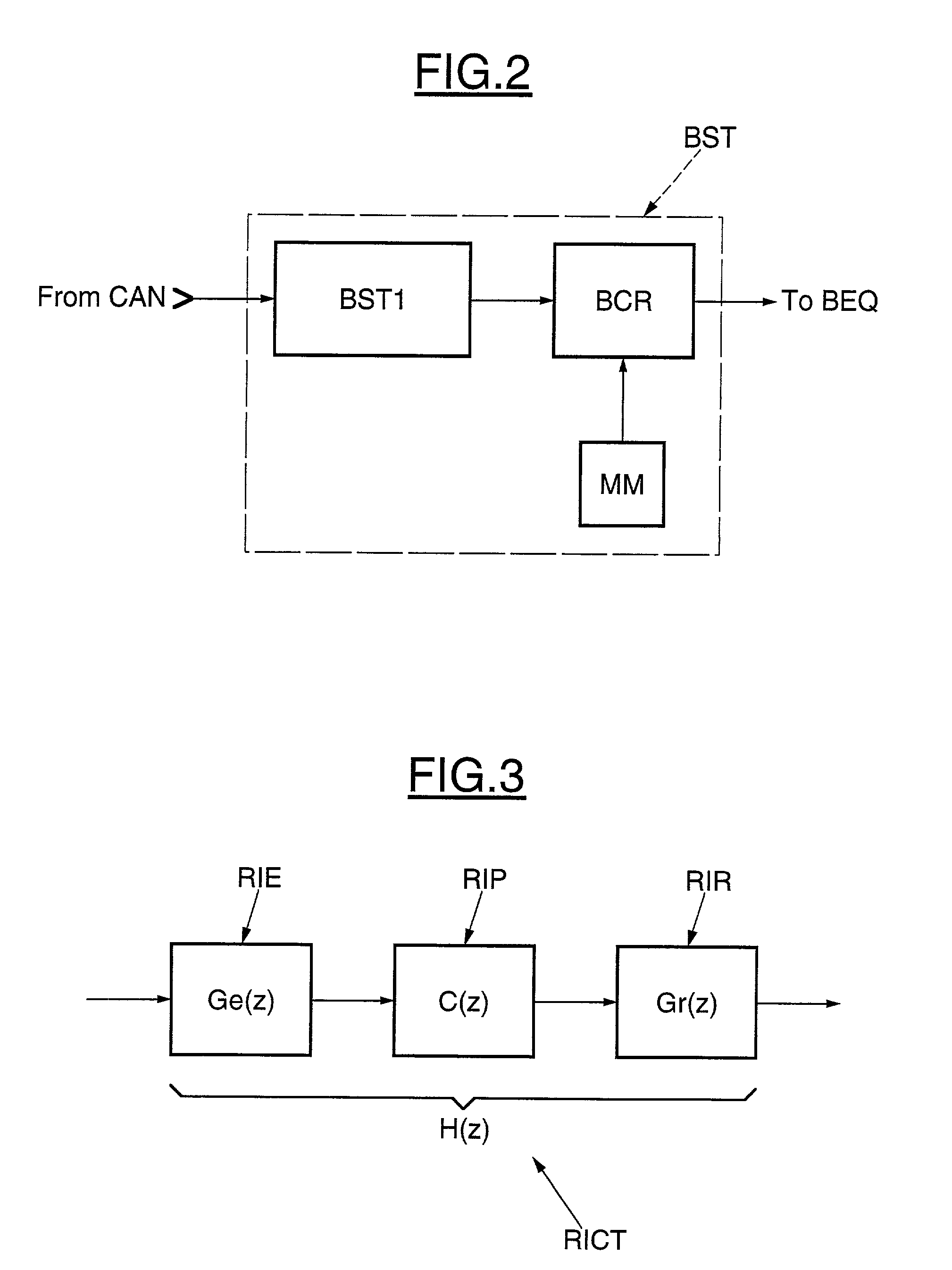
"The present invention provides an improvement to channel estimation that can be applied equally well to learned estimates and blind estimates. This improvement involves making a first estimate of the impulse response of the channel, then correcting this estimate by taking account of the known elements of the sending and receiving means, such as the modulators, demodulators, and filters. The correction is done by multiplying the coefficients of a transformation matrix with the coefficients of the first estimate, which is independent of the information transmitted. This invention requires the storage of only a single transformation matrix, which is independent of the training sequences used. The invention also provides a device, a computer program, and a storage device for implementing the estimation process."

Problems solved by technology

A fundamental factor limiting the performance of a digital communication system is the phenomenon known as inter-symbol interference, which is well known by a person skilled in the art.
Moreover, this interference between symbols is produced not only by the propagation between the sender and the receiver, but also by the sending / receiving devices themselves, such as the modulator, filter, etc.
During communications with interference between symbols, the problem arises on estimating the impulse response of the transmission channel.
However, such a method has drawbacks.
Another drawback resides in the fact that such a method is not applicable to so-called blind channel estimates, that is to say, when training sequences are not available.

Method used


Image

  • Process and device for estimating the impulse response of an information transmission channel, in particular for a cellular mobile telephone
  • Process and device for estimating the impulse response of an information transmission channel, in particular for a cellular mobile telephone
  • Process and device for estimating the impulse response of an information transmission channel, in particular for a cellular mobile telephone

Examples


Embodiment Construction

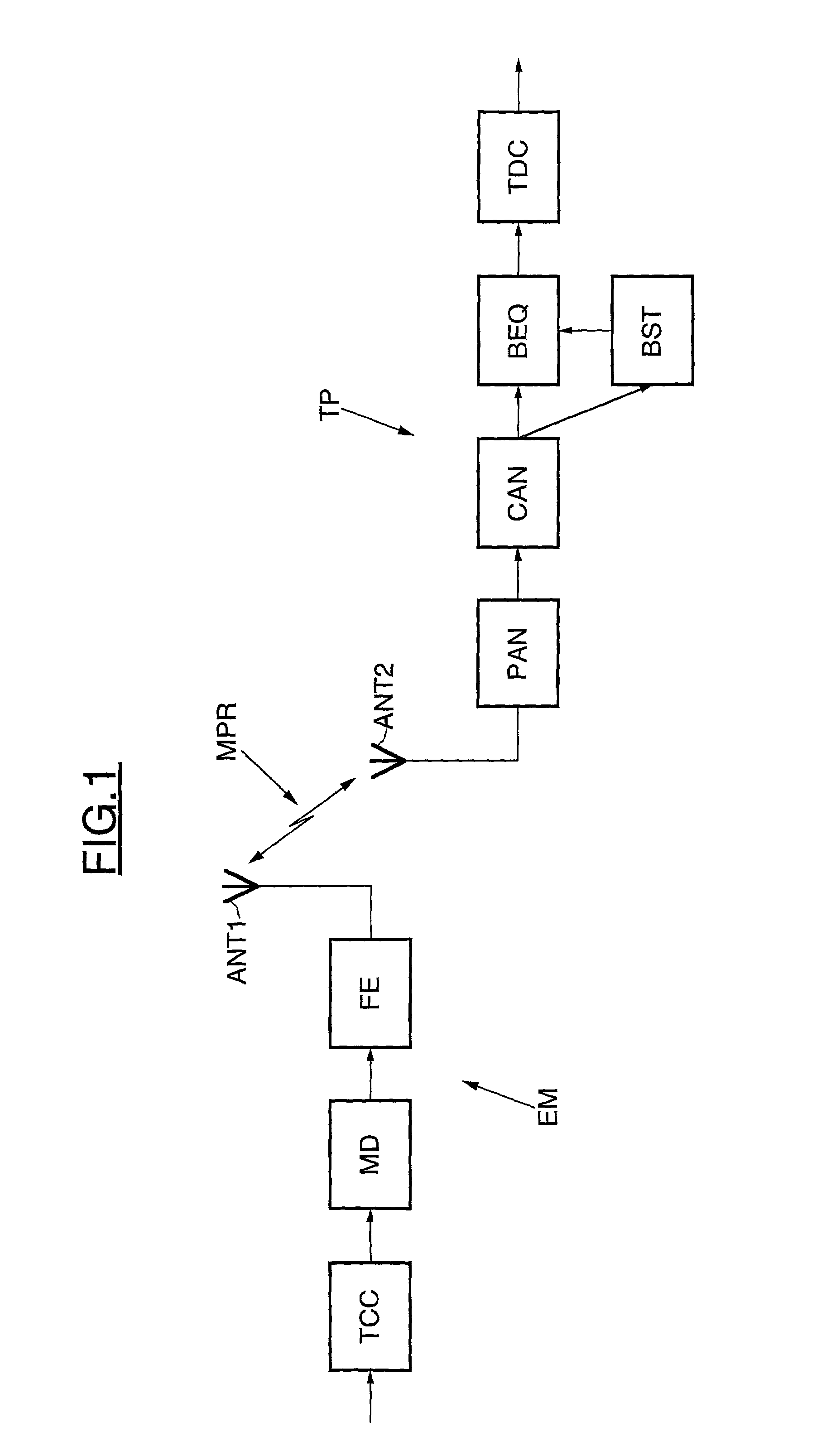
[0030]It is now assumed, referring more particularly to FIG. 1, that the invention is applied to the domain of cellular mobile telephones, for example, such as those of the GSM network, for example. In FIG. 1, the reference EM designates a sender or transmitter comprising upstream a coding block TCC for receiving the useful data to be transmitted, such as speech for example, and performing in particular channel coding conventional processing for introducing redundancies into the data stream. The output from the TCC block includes binary information blocks.

[0031]The TCC block is conventionally followed by a modulator performing, for example, a quadrature modulation of the QPSK or 8PSK type, according to terminology well known to a person skilled in the art, and transforming the binary signal into an analog signal. This analog signal is then filtered in a send filter FE before being sent towards the receiver via an antenna ANT1. The means of propagation MPR between a sender EM and a r...


PUM


Abstract

A first estimate is made of the impulse response of the channel considered as a whole, then this first estimate is corrected independently of the information transmitted for obtaining a corrected final estimate of the impulse response of the channel. This is done by taking account of the fact that the impulse response of the sender and the impulse response of the receiver are known.

Description

FIELD OF THE INVENTION[0001]The invention relates to the transmission of digital information, and more particularly but not exclusively, within a cellular mobile telephone domain according to the GSM (Global System for Mobile Communication) standard.[0002]The invention relates more particularly to the estimation of the impulse response of a transmission channel conveying information from a sender to a receiver via a means of propagation. The means of propagation may be air for cellular mobile telephones, or any other means of propagation, such as a cable in other applications, for example.BACKGROUND OF THE INVENTION[0003]A fundamental factor limiting the performance of a digital communication system is the phenomenon known as inter-symbol interference, which is well known by a person skilled in the art. Inter-symbol interference causes at the receiver level temporal occupation of each symbol or bit transmitted, which is longer than the initial duration of the symbol. This is also re...

Claims


Application Information

Patent Timeline
Patent Type & Authority Patents(United States)
IPC IPC(8): H04B17/00H04B3/46H04Q1/20H04L27/22H04B3/06H04L25/02
CPCH04L25/0202
Inventor CHAPPAZ, DAVID
Owner STMICROELECTRONICS SRL
Learn More