Engine fuel injection valve and manufacturing method for nozzle plate used for the same injection valve

a technology of fuel injection valve and manufacturing method, which is applied in the direction of fuel injecting pump, machine/engine, manufacturing tools, etc., can solve the problems of reducing reliability, limiting the granulation of injected fuel into minute particles, and easy clogging of nozzle holes, so as to improve combustion. the effect of

Inactive Publication Date: 2006-01-31
HITACHI LTD
View PDF6 Cites 26 Cited by
  • Summary
  • Abstract
  • Description
  • Claims
  • Application Information

AI Technical Summary

Benefits of technology

[0011]An automotive vehicular engine field has demanded that since as each hole diameter of the nozzle holes becomes finer (smaller), the particles of the injected

Problems solved by technology

However, even if the nozzle holes are formed to become small and a minute amount of foreign matters is slightly mixed, the nozzle holes are easier to be clogged.
Hence, there is a limitation to granulate injected fuel into minute part

Method used


Image

  • Engine fuel injection valve and manufacturing method for nozzle plate used for the same injection valve
  • Engine fuel injection valve and manufacturing method for nozzle plate used for the same injection valve
  • Engine fuel injection valve and manufacturing method for nozzle plate used for the same injection valve

Examples


second embodiment

[0091]In the second embodiment, both surfaces of the plate material are ground in the plate thickness direction.

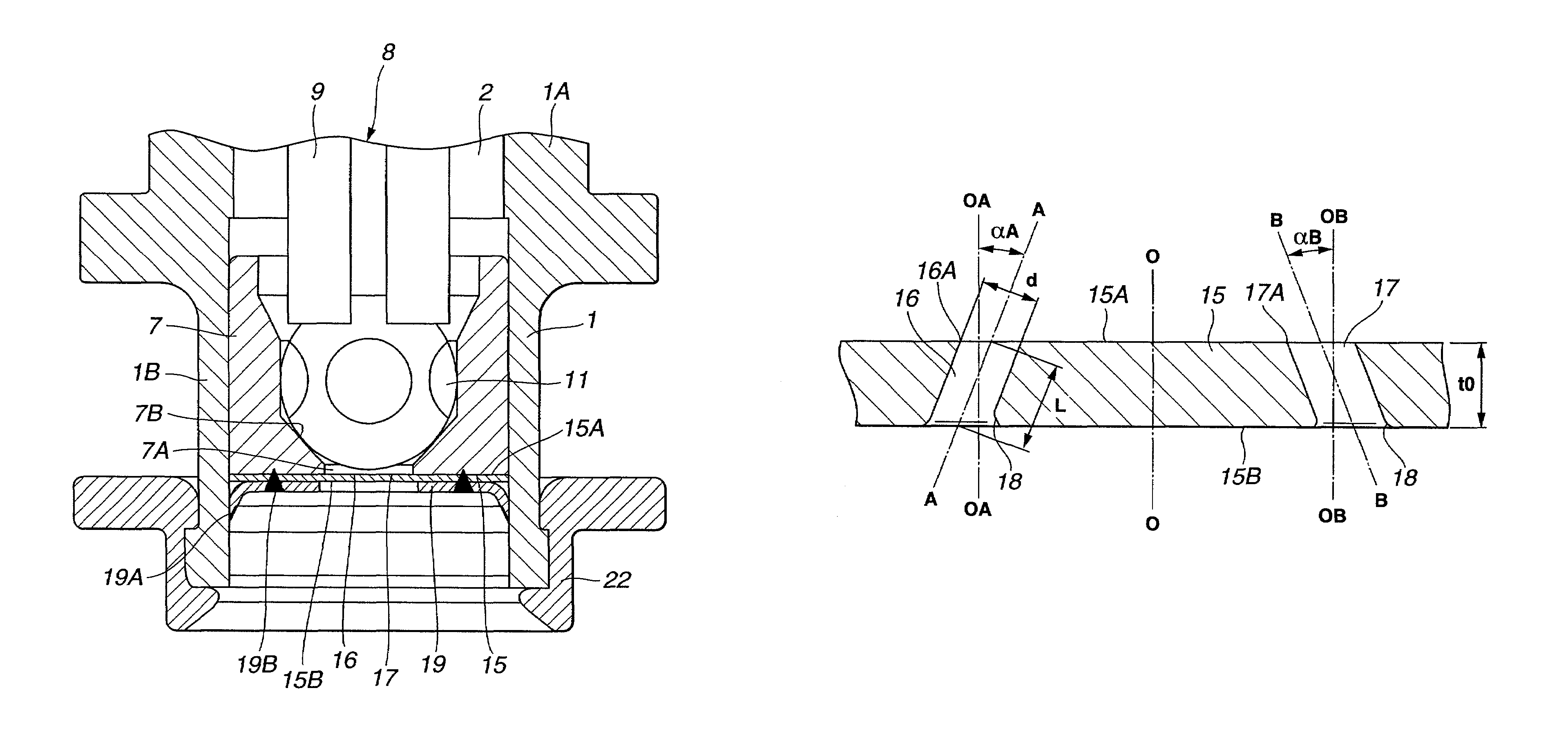
[0092]The nozzle plate 41 manufactured using the manufacturing method in the second embodiment is of, for example, the circular metallic plate, in the same manner as the nozzle plate described in the first embodiment. On the nozzle plate 42, the plurality of left nozzle holes 42 and right nozzle holes 43 are punched. Each nozzle hole 42 and 43 is a straight penetrated hole inclined by the predetermined inclination angle with respect to the plate thickness direction.

[0093]Each left nozzle hole 42 is provided with inflow opening ends 42A opened to one side surface 41A of the nozzle plate 41 positioned at the inflow side of fuel and the outflow opening ends 42B opened to the other side surface 41B positioned at the outflow position of fuel. In addition, the right nozzle holes 43 are positioned with opening ends 43A and 43B positioned on the outflow side of fuel. The opening e...

first embodiment

[0097]Next, during the punch process shown in FIG. 14, the punching is carried out for the plate material 51 in the substantially same manner as the punch process carried out in the first embodiment so that the plurality of penetrated holes 52 and 53 are punched. In this case, a predetermined clearance C of, for example, about 1 through 10 μm is formed as a circular gap between punch holes 54A and 54B of the die 54 used in the punching process and punch 55.

[0098]During this process, the punch 55 is penetrated in the injection direction of fuel from the one side surface 51A of the plate material 51 toward the other side surface 51B. Consequently, a convexed shear droop 56 is often formed on the surrounding portion of the inflow opening ends of the through holes 52 and 53. Defects 57 and facture-plane 58 are often formed in the proximities to the outflow opening ends.

[0099]During the polish process shown in FIG. 15, the one surface (front) 51A of the plate material and the other (rear...


PUM


Abstract

In a fuel injection valve, a substantially arc-shaped chamfered portion in a substantially arc shape of cross section is formed on an edge of an inner wall portion of each opening end of a corresponding nozzle hole of a nozzle plate to further expand a whole diameter of an injection stream of fuel passed through a plurality of obliquely penetrated nozzle holes. In a manufacturing method for the nozzle plate, circulating a fluid mixed with an abrasive through each nozzle hole is carried out to polish opening ends of the respective nozzle holes which are faced against the external of the fuel injection valve in a form of substantially arc shape of cross section with the abrasive. Furthermore, grinding the respective major surfaces of a punched plate material which becomes the nozzle plate together with vicinities to the respective opening ends of the nozzle holes is carried out.

Description

BACKGROUND OF THE INVENTION[0001]a) Field of the Invention[0002]The present invention relates to a fuel injection valve suitable for a fuel injection into an internal combustion engine of an automotive vehicle and a manufacturing method for a nozzle plate to be assembled into the fuel injection valve.[0003]b) Description of the Related Art[0004]A general fuel injection valve (normally called, fuel injector but also called fuel injection valve) used in an automotive engine includes a cylindrical valve casing having a fuel passage in its axial direction; a valve seat member having a valve seat and an injection outlet opening, the valve seat being disposed on an inner periphery of the valve casing at a tip end so as to enclose the injection outlet opening; a nozzle plate disposed at the tip of the valve casing so as to be faced against the injection outlet opening of the valve seat member and having a plurality of nozzle through-holes to inject fuel toward an external to the valve casi...

Claims


Application Information

Patent Timeline
IPC IPC(8): B05B1/00B24B15/04B24B31/116F02M51/06F02M51/08F02M61/16F02M61/18
CPCB24B15/04B24B31/116F02M61/1846F02M61/1853F02M61/168Y10S239/90
Inventor KOBAYASHI, TAKAYUKIYANASE, MASATOSHIHIRATA, HIROAKINAKAGANE, HIROKI
Owner HITACHI LTD
Why Eureka
Try Eureka