Hydrogen storage tank

a technology of hydrogen storage tank and hydrogen absorption material, which is applied in the direction of physical/chemical process catalyst, lighting and heating apparatus, separation process, etc., can solve the problems of small amount of hydrogen absorption per unit volume and slow rate of hydrogen desorption, so as to improve hydrogen absorption efficiency and increase the amount of hydrogen absorption

Inactive Publication Date: 2006-01-31
HONDA GIEKN IND
View PDF12 Cites 33 Cited by
  • Summary
  • Abstract
  • Description
  • Claims
  • Application Information

AI Technical Summary

Benefits of technology

[0012]In the above configuration, the hydrogen absorption and desorption surface is on the outer peripheral surface of the hydrogen storage section and is surrounded by the hydrogen passage, which permits enlarging an area for hydrogen absorption and desorption per unit volume and thereby increases the amount of hydrogen absorption per unit volume.
[0013]Further, there is provided a fluid passage for passing cooling fluid through the hydrogen absorption material aggregate. During hydrogen absorption, since the hydrogen adsorption proceeds from the outer peripheral side, that is, inwardly from the hydrogen absorption and desorption surface,...

Problems solved by technology

The conventional double cylinder tank, however, has a problem in that its narrow hydrogen passage results in a small area for hydrogen absorption and desorp...

Method used


Image

  • Hydrogen storage tank
  • Hydrogen storage tank
  • Hydrogen storage tank

Examples


first embodiment

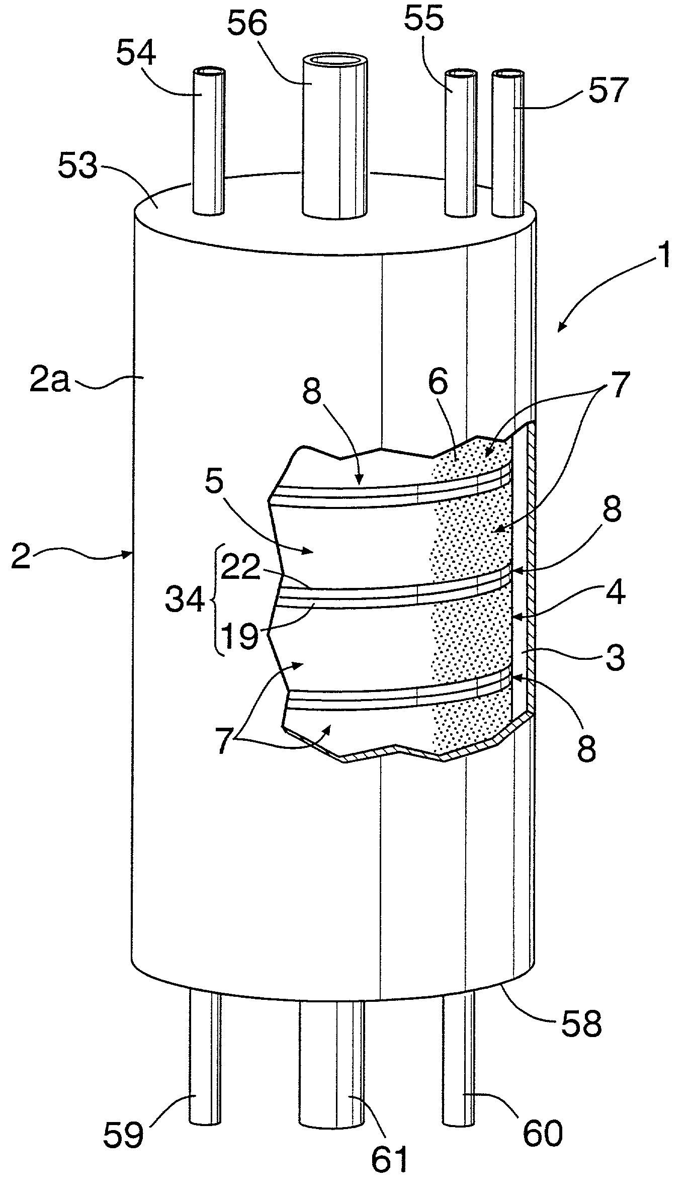
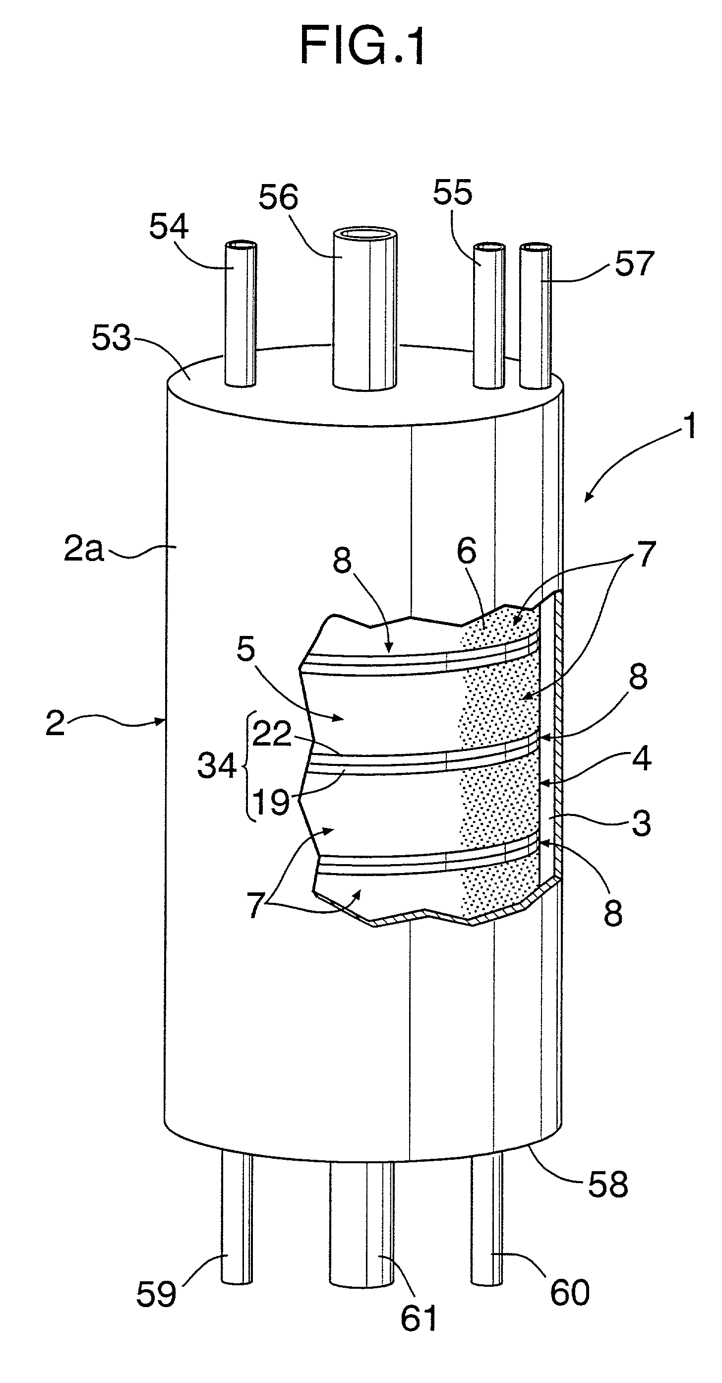
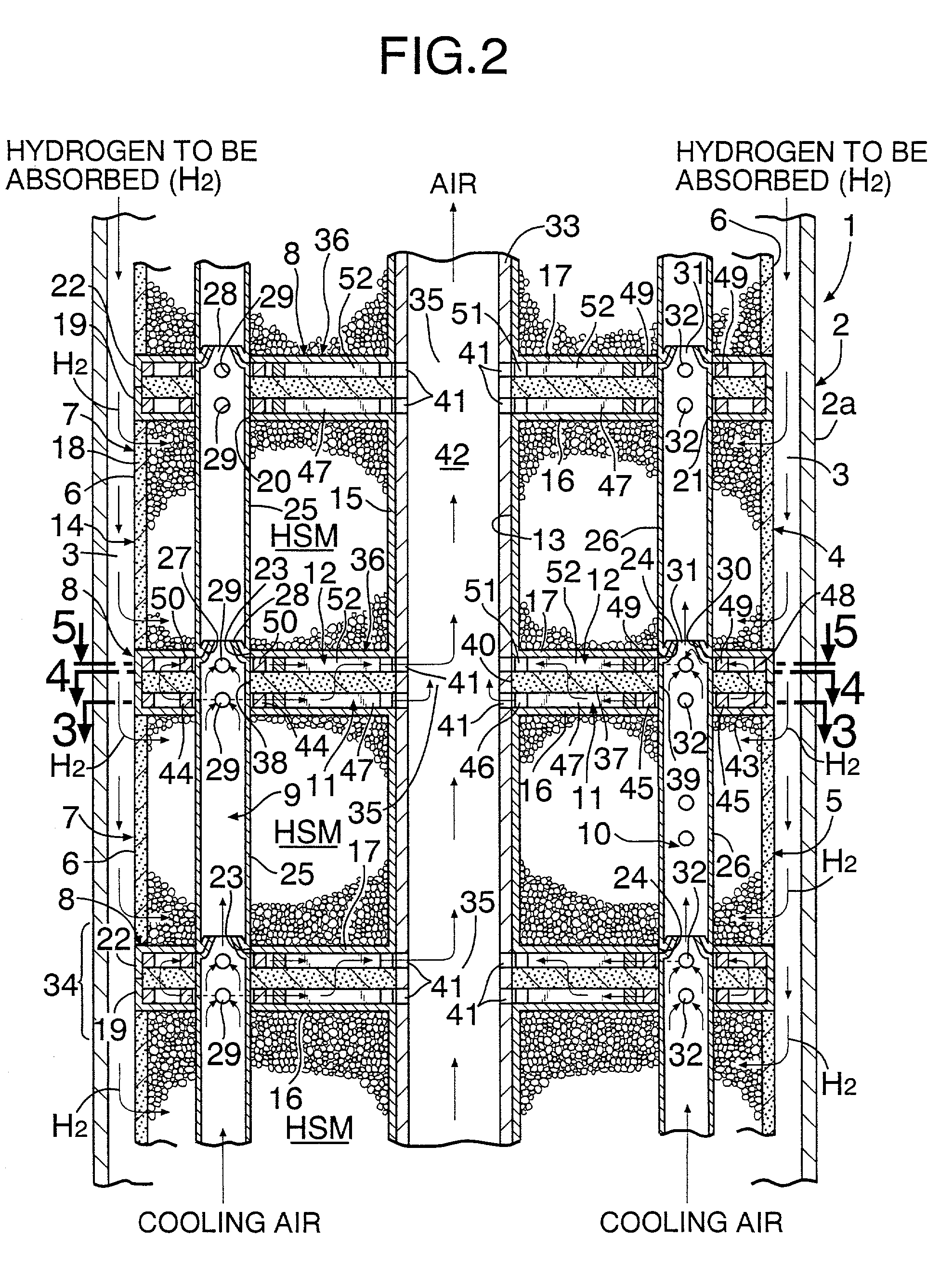
[0037]FIGS. 1 to 6A show a hydrogen storage tank 1 according to the present invention. The hydrogen storage tank 1 includes a pressure-resist outer cylinder 2 made of stainless steel and having a circular cross section. At least one (one in this embodiment) cylindrical hydrogen storage module 4 is accommodated within the outer cylinder 2 in such a manner as to be spaced apart from an inner peripheral surface of an outer peripheral wall 2a of the outer cylinder 2 to provide a hydrogen passage 3 therebetween.

[0038]The cylindrical hydrogen storage module 4 comprises a lamination 5 of a plurality of hydrogen storage units 7, each filled with powdery hydrogen absorption materials (HSM) and having a hydrogen absorption and desorption surface 6 on at least a part of its outer peripheral surface (a whole outer peripheral surface in this embodiment), while interposing a heating / cooling element 8 between adjacent units 7. Hydrogen storage alloy (for example, a Mg alloy such as Mg2Ni) or carbo...

second embodiment

[0064]FIGS. 7 and 8 show a hydrogen storage tank 1 according to the present invention. In each hydrogen storage unit 7 of this embodiment, a plurality of fins 62, made of materials with excellent thermal conductivity, such as copper and Ni, are arranged in the cylinder 14 so as to radially extend from a hollow shaft 15. Each fin 62 is joined to the hollow shaft 15 and the top and bottom walls 16 and 17 by welding. Also, each fin 62 contacts the heating and cooling element 8.

[0065]The fins 62 are embedded in powdery hydrogen absorption material HSM to contribute to the cooling and heating of the hydrogen absorption material HSM, strengthen the cylinder 14, and prevent uneven distribution of the powdery hydrogen absorption material HSM. In this case, the inflow ports 29, 32, and the outflow ports 41 may be positioned in the same manner as in the embodiment shown in FIG. 6B, and hydrogen for burning and oxygen (air) may be used as heating fluid.

third embodiment

[0066]FIG. 9 shows a hydrogen storage tank 1 according to the present invention. In this embodiment, a plurality of hydrogen storage modules 4 are arranged in the pressure-resist outer cylinder 2 to have a close packed structure in order to increase the amount of hydrogen absorption.


PUM


Abstract

A hydrogen storage tank has an outer cylinder and a cylindrical hydrogen storage module within the outer cylinder spaced apart from an inner peripheral surface of the outer cylinder to provide a hydrogen passage therebetween. The cylindrical hydrogen storage module includes a lamination having a plurality of hydrogen storage units filled with powdery hydrogen absorption material and a hydrogen absorption and desorption surface on an entire outer peripheral surface, while interposing a heating/cooling element between ones of adjacent units. First and second main passages penetrate the lamination in a lamination direction of the units, and permit heating fluid and cooling fluid to flow therethrough. Sub passages branch from the main passages and extend over within each of the heating/cooling elements.

Description

BACKGROUND OF THE INVENTION[0001]1. Field of the Invention[0002]The present invention relates to a hydrogen storage tank for absorbing and desorbing hydrogen.[0003]2. Description of the Prior Art[0004]An example of a conventionally known hydrogen storage tank that absorbs and desorbs hydrogen is a double cylinder tank. The double cylinder tank has an inner cylinder which accommodates a hydrogen storage alloy and is provided, around its longitudinal axis, with a hydrogen passage for passing hydrogen to be absorbed and to be desorbed therethrough as well as to provide a passage for heating fluid and cooling fluid between the inner and outer cylinders.[0005]The conventional double cylinder tank, however, has a problem in that its narrow hydrogen passage results in a small area for hydrogen absorption and desorption per unit volume, thereby causing small amounts of hydrogen absorption per unit volume and a slow rate of hydrogen desorption because of heating inefficiency.SUMMARY OF THE I...

Claims


Application Information

Patent Timeline
IPC IPC(8): B01J8/02F17C11/00B01D53/04
CPCB01D53/0407B01D53/0431B01D53/0438B01D2259/4525B01D2259/4009B01D2259/40098B01D2257/108F17C11/005C01B3/0005Y02E60/32
Inventor SUZUKI, TAKANORIKANOYA, IZURUHOSOE, MITSUYA
Owner HONDA GIEKN IND
Why Eureka
Try Eureka