
Symbology for representing aircraft position

a technology of aircraft position and symbology, applied in the field of programmatic symbology, can solve the problems of increasing the amount of monitoring required, less than optimal flight control, and complex systems of aircraft, including helicopters

Inactive Publication Date: 2006-01-31
ROGERS STEVEN P +1
View PDF3 Cites 37 Cited by
  • Summary
  • Abstract
  • Description
  • Claims
  • Application Information

AI Technical Summary

Benefits of technology

[0019]An advantage of the present invention is that that maximum use is made of ambient visual information so that orientation is pre-attentive and automatic.
[0020]A further advantage of the present invention is that it is particularly useful to represent the aircraft's operations during non-visual flight conditions such as night and / or adverse weather flight operations.
[0021]Another advantage of the present invention is that the symbology's geometric form is displayed utilizing various user-definable visual attributes to identify distinct pieces of data within the symbology set.
[0022]Yet another advantage of this invention is because this symbology retains the world-as-ground frame of reference, the pilot never loses his spatial orientation even when there are temporary unobserved orientation changes of the aircraft.

Problems solved by technology

Aircraft, including helicopters, are highly complex systems comprised of a large number of complex, integrated subsystems that requires frequent monitoring for safe aircraft operation.
Additional flight complications such as nap-of-the-earth (NOE), adverse weather, and / or night flying add to the importance of aircraft status data, and also increases the amount of monitoring required.
The task of monitoring the status of the various aircraft subsystems may conflict with the tasks of maintaining continual spatial and situational awareness of the external world.
Such diversions may lead to losses, in varying degrees, of spatial and / or situational awareness of the external world, which, in turn, may lead to less than optimal flight control, especially during high pilot workload flight operations.

Method used


Image

  • Symbology for representing aircraft position
  • Symbology for representing aircraft position
  • Symbology for representing aircraft position

Examples


Embodiment Construction

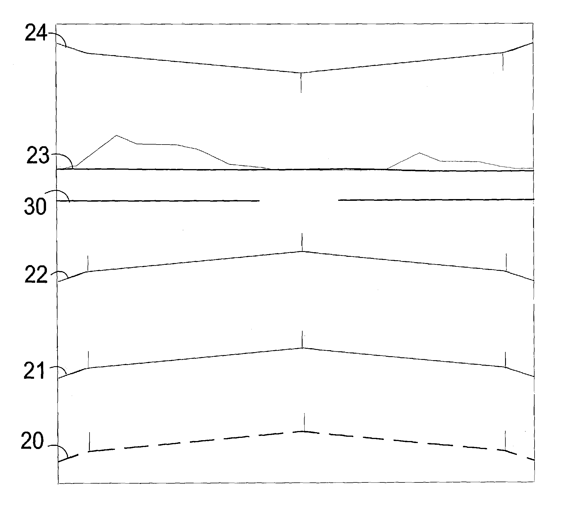
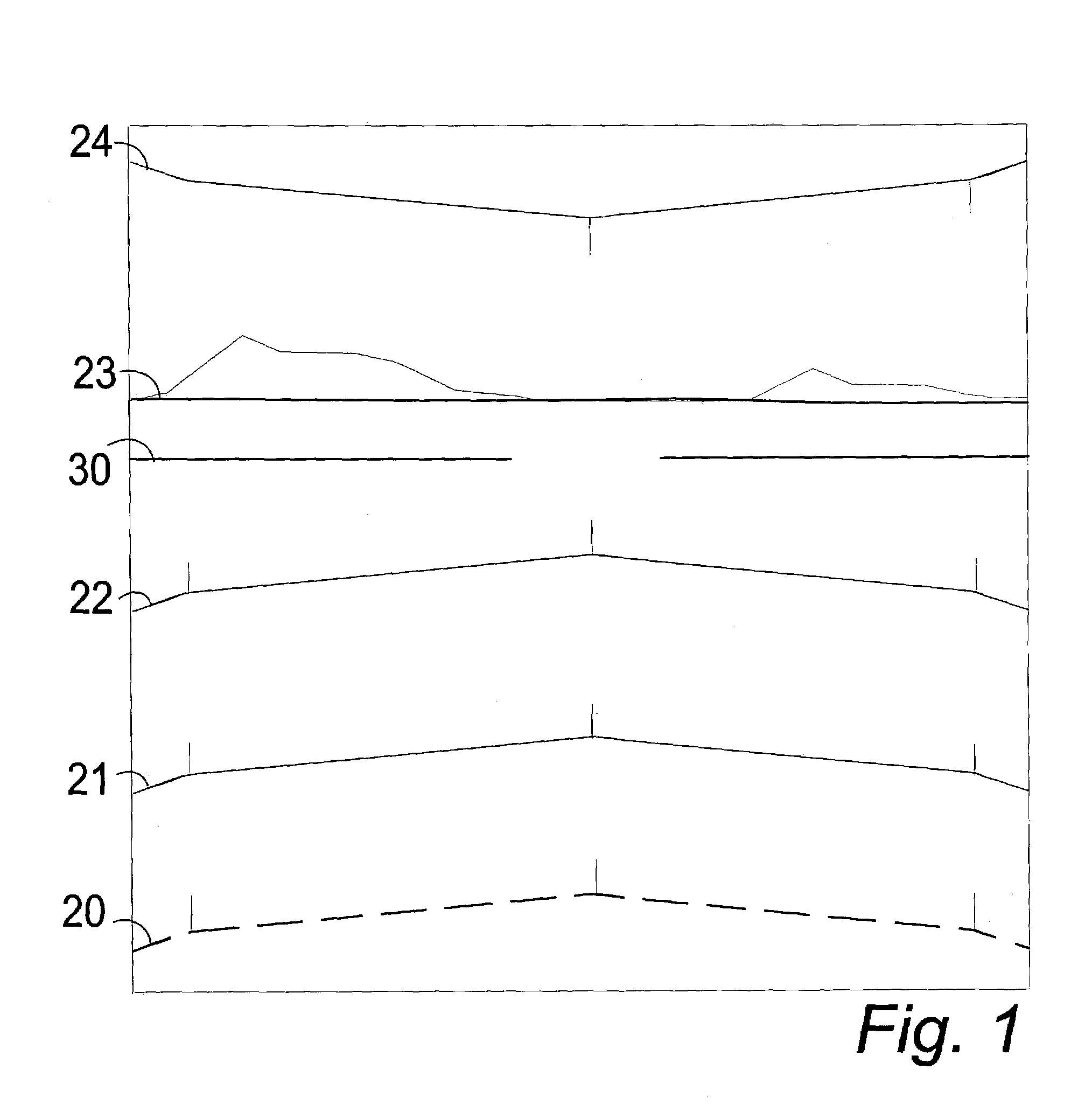
[0028]In FIGS. 1–4 a symbology system comprises a means for programming information gathered from flight instruments relative to an aircraft's flight position and creating symbology representing the flight position in the visual field of a pilot as seen in FIGS. 1 and 4.

[0029]A programmable means, such as an onboard programmable computer in communication with flight position instruments and in communication with the pilot's display, as seen in FIGS. 1 and 4, gathers flight position information in real time about the aircraft from a number of instruments on the aircraft and using the flight position information, creates symbology representing the flight position information in the visual field of a pilot of the aircraft, as shown in FIGS. 1 and 4.

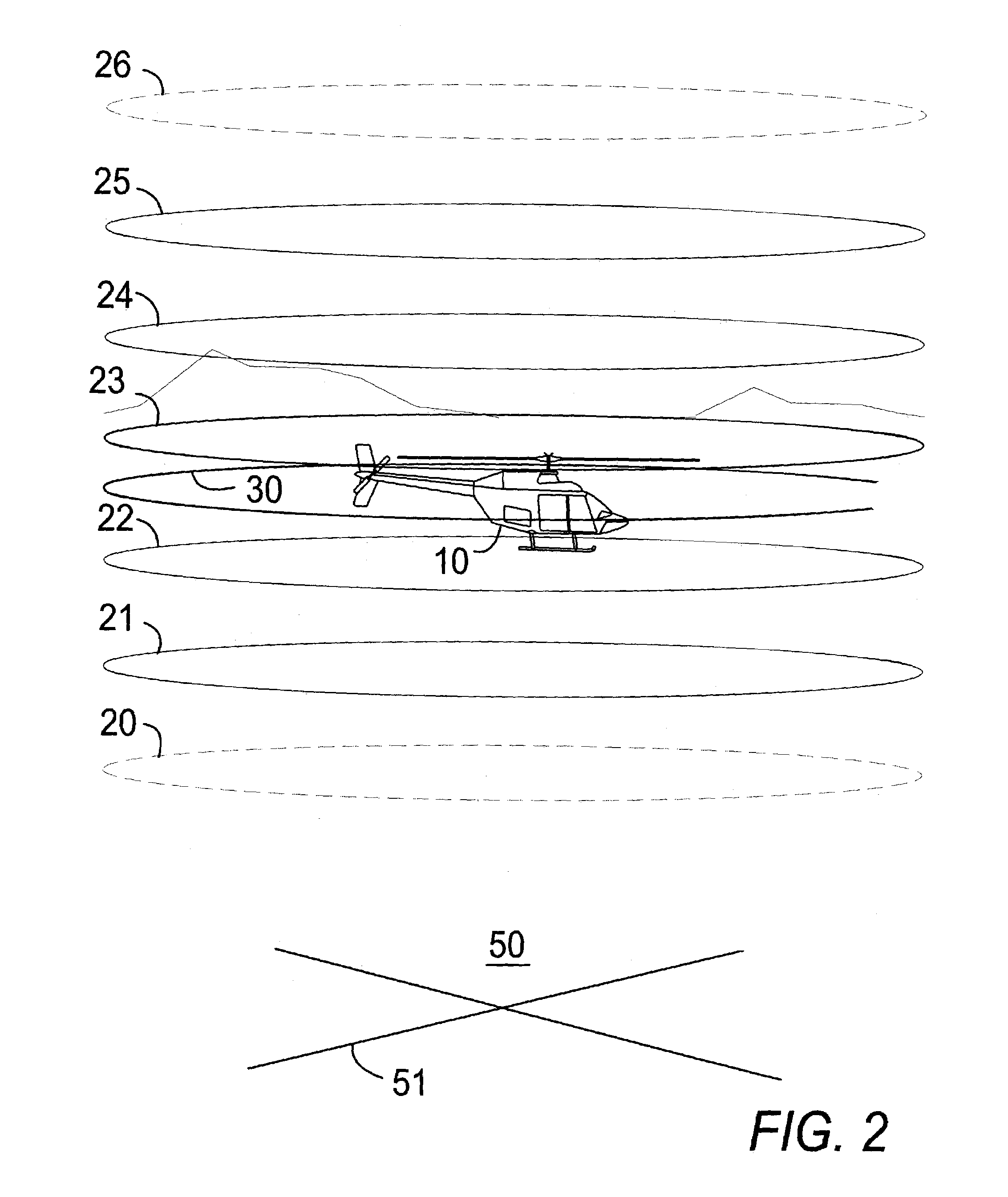
[0030]The symbology comprises an image representing a virtual figure, such as a cylinder represented by peripheral spaced lines 20–26 as shown in FIGS. 2 and 3, appearing to surround the aircraft, such as a helicopter 10, and travel with the...


PUM


Abstract

A symbology system uses programmable software in a computerized system interacting with the altitude, attitude, air speed, and other flight indicators of an aircraft to create symbology in the pilot's display seen in the field of view of the pilot. The symbology represents a virtual geometric solid form, such as a vertical cylinder, always appearing perpendicular to the horizon and moving across the terrain with the aircraft in the center of the form. The pilot sees a front portion of a virtual series of horizontal circles or other shapes, spaced by a programmable distance, symbolizing the geometric solid form appearing to surround the aircraft. The geometric form references the world as-ground for use in recognizing the attitude of the aircraft-as-figure. On landing, the form appears to stop at the ground and the aircraft appears to descend within it. A virtual bank indicator line changes orientation to the geometric solid corresponding to the attitude change of the aircraft relative to the horizon.

Description

BACKGROUND OF THE INVENTION[0001]1. Field of the Invention[0002]The present invention relates to displays for pilots of aircraft and in particular to a programmable symbology for defining a geometric form in the visual field of the pilot providing a virtual representation of a geometric shape surrounding the aircraft providing information to the pilot about the position and orientation of the aircraft and its surroundings.[0003]2. Description of the Prior Art[0004]Aircraft, including helicopters, are highly complex systems comprised of a large number of complex, integrated subsystems that requires frequent monitoring for safe aircraft operation. Each of these subsystems generates a significant amount of status data. Additional flight complications such as nap-of-the-earth (NOE), adverse weather, and / or night flying add to the importance of aircraft status data, and also increases the amount of monitoring required. These types of flight operations require the pilot to maintain a cont...

Claims


Application Information

Patent Timeline
IPC IPC(8): G08G1/095G01C23/00
CPCG01C23/00
Inventor ROGERS, STEVEN P.ASBURY, CHARLES N.
Owner ROGERS STEVEN P
Learn More