
Hybrid-mode horn antenna with selective gain

a horn antenna and hybrid-mode technology, applied in the field of horn antennas, can solve the problems of small intrinsic bandwidth of endfire horns, less mechanical robustness, and other non-hybrid-mode horns that only work for limited aperture sizes, and achieve simple mechanically, facilitate boundary conditions design, and large bandwidth

Active Publication Date: 2006-01-31
LOCKHEED MARTIN CORP
View PDF9 Cites 290 Cited by
  • Summary
  • Abstract
  • Description
  • Claims
  • Application Information

AI Technical Summary

Benefits of technology

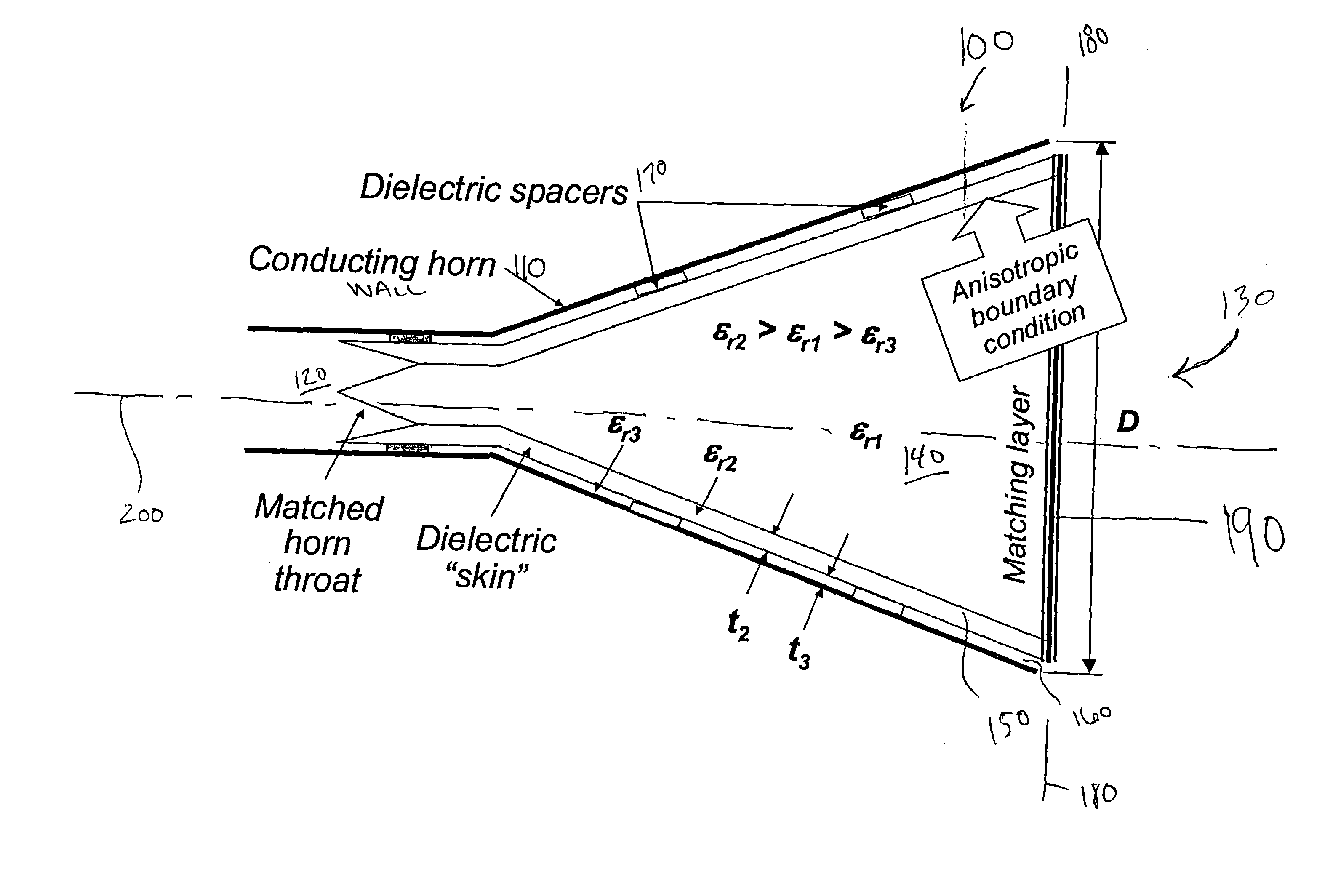
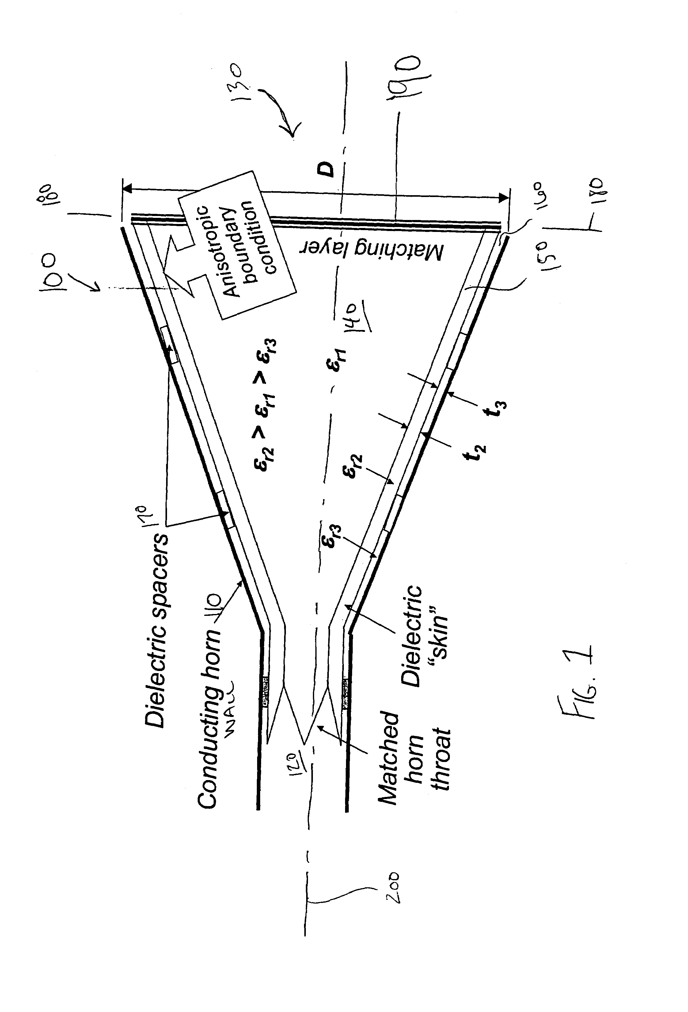
[0009]The present invention provides a new class of hybrid-mode horn antennas. The present invention facilitates the design of boundary conditions between soft and hard, supporting modes under balanced hybrid condition with uniform as well as tapered aperture distribution. In one embodiment, the horn is relatively simple mechanically, has a reasonably large bandwidth, can support linear as well as circular polarization, and can be designed for a wide range of aperture sizes.
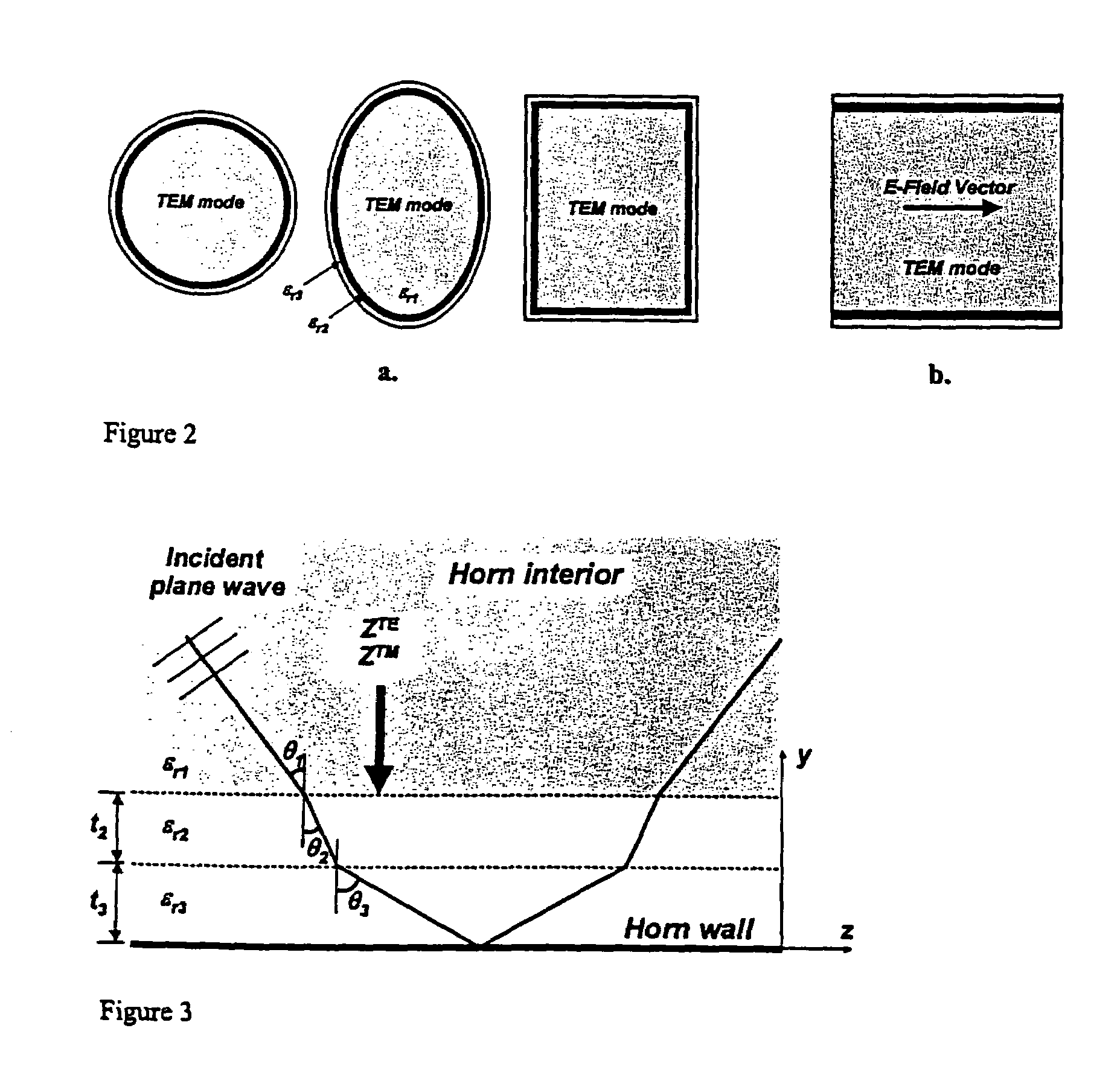
[0010]In one embodiment, antennas of the present invention are dielectric-loaded circularly or linearly polarized hybrid-mode horn antennas which can be designed to a desired high directivity (gain) and low cross-polarization (axial ratio) over a wide frequency band. In one embodiment of the present invention, an antenna comprises a dielectric core inside a horn, where the core has two or more dielectric layers, and where the core is separated from the horn wall. The antenna boundary conditions facilitate a balanced hybrid-mode in the inner dielectric region with zero or negligible cross-polarization at the design frequency. With proper design, this mode can be close to a TEM mode with uniform or nearly uniform aperture distribution and consequently high gain.
[0011]Horn antennas of the present invention will have a wide range of uses. For example, in one embodiment the horn is used as an element in a limited scan phased array where a larger element aperture size is needed. They may provide high aperture efficiency and low grating lobes. In another embodiment, the horns are used as feed elements for reflector antennas or in quasi-optical amplifier arrays. It could be particularly useful in millimeter wave applications. Embodiments having a flat top pattern design make it a candidate earth coverage horn on-board satellites and a candidate feed for reflector antennas with enhanced directivity.

Problems solved by technology

However, these endfire horns also have a small intrinsic bandwidth and may be less mechanically robust.
However, these as well as the other non hybrid-mode horns only work for limited aperture size, typically under 1.5 to 2λ.

Method used


Image

  • Hybrid-mode horn antenna with selective gain
  • Hybrid-mode horn antenna with selective gain
  • Hybrid-mode horn antenna with selective gain

Examples


Embodiment Construction

[0038]In one embodiment, a new and mechanically simple dielectric loaded hybrid-mode horn is presented. In alternative embodiments of the present invention, the horn satisfies hard boundary conditions, soft boundary conditions, or boundaries between hard and soft under balanced hybrid conditions (low cross-polarization). Like other hybrid mode horns, the present design is not limited in aperture size. In some embodiments, design curves were developed based on a plane wave model, and radiation performance was computed based on a cylindrical waveguide model. In one embodiment, aperture efficiency of about ninety-four percent (94%) has been computed at the design frequency for a 3.38λ aperture with hard boundary condition and a dielectric constant of 4.0. The same horn with a dielectric constant of 2.5 can provide higher than about eighty-nine percent (89%) aperture efficiency and under −30 decibels (dB) cross-polarization over about a fifteen percent (15%) frequency range. Predicted p...


PUM


Abstract

The present invention provides a new class of hybrid-mode horn antennas. The present invention facilitates the design of boundary conditions between soft and hard, supporting modes under balanced hybrid condition with uniform as well as tapered aperture distribution. In one embodiment, the horn antenna (100) is relatively simple mechanically, has a reasonably large bandwidth, supports linear as well as circular polarization, and is designed for a wide range of aperture sizes.

Description

RELATED APPLICATIONS[0001]The present application claims priority from U.S. Provisional Application No. 60 / 440,715, filed Jan. 16, 2003, entitled “Dielectric-Loaded Hybrid-Mode Horn Antenna with Selectable or High Gain and Large Bandwidth”; and from U.S. Provisional Application No. 60 / 480,369, filed Jun. 19, 2003, entitled “Hybrid-Mode Horn Antenna with Selective Gain”, the complete disclosures of which are incorporated herein by reference for all purposes.BACKGROUND OF THE INVENTION[0002]The present invention is directed generally to horn antennas, and more specifically to a new class of hybrid-mode horn antennas having selective gain.[0003]Maximum directivity from a horn antenna is obtained by uniform amplitude and phase distribution over the horn aperture. Such horns are denoted as “hard” horns. They can support the transverse electromagnetic (TEM) mode, and apply to linear as well as circular polarization. They are characterized with hard boundary impedances:Zz=−Ez / Hx=0 and Zx=E...

Claims


Application Information

Patent Timeline
Patent Type & Authority Patents(United States)
IPC IPC(8): H01Q13/02
CPCH01Q13/025
Inventor LIER, ERIK
Owner LOCKHEED MARTIN CORP
Learn More