Hybrid drive system wherein clutch is engaged when engine speed has exceeded motor speed upon switching from motor drive mode to engine drive mode

a hybrid drive and clutch technology, applied in the direction of engine-driven generators, machines/engines, process and machine control, etc., can solve the problems of reducing the drive force of the known hybrid-vehicle drive system, not being able to control the vehicle in the manner described above, etc., and achieve the effect of improving the manner

Inactive Publication Date: 2006-02-07
TOYOTA JIDOSHA KK
View PDF28 Cites 38 Cited by
  • Summary
  • Abstract
  • Description
  • Claims
  • Application Information

AI Technical Summary

Benefits of technology

[0008]It is therefore an object of the present invention to provide a hybrid-vehicle drive system which is improved in the manner of control in which the vehicle drive mode is switched from the motor-drive mode to the engine-drive mode.
[0010]In the hybrid drive system constructed according to the first aspect of this invention described above, the second-clutch control means is operated upon switching of the vehicle drive mode from the forward motor drive mode (established by the forward-motor-drive control means) to the engine drive mode (established by the forward-engine-drive control means). The second-clutch control means is arranged to engage the second clutch only after the operating speed of the engine has exceeded that of the electric motor. This arrangement permits a smooth transition of the vehicle drive mode to the engine drive mode, for thereby rapidly increasing the vehicle drive force, without a reduction of the vehicle drive force during the transition, where the transition to the engine drive mode is required due to an increase in the operating amount of the accelerator pedal, for example. That is, if the second clutch were engaged while the engine speed is lower than the motor speed, the vehicle drive force would be partly consumed by an increase of the engine speed to the motor speed.
[0025]In the hybrid drive system constructed according to the third aspect of this invention described above, the non-cranking engine starting means is operated when the vehicle drive mode is required to be changed from the motor drive mode to the engine drive mode. The non-cranking engine starting means is arranged to start the engine by merely controlling the fuel injecting state of the engine and other states of the starting of the engine, without cranking the engine, when the engine speed is higher than the predetermined threshold. Where the operating amount of the accelerator pedal is increased immediately after the vehicle drive mode has been changed from the engine drive mode to the motor drive mode, for instance, the vehicle drive mode is required to be changed to the engine drive mode again. In this case, the engine is started without cranking, so that the transition to the engine drive mode can be rapidly achieved. Where the engine is started by cranking with an engine starter, the pinion of the starter must be brought into meshing engagement with the ring gear provided on the flywheel of the engine, so that the pinion cannot be held in meshing engagement with the ring gear until the engine speed has been lowered to a predetermined value. Accordingly, the starting of the engine and the transition to the engine drive mode are delayed. This delay is not encountered according to the third aspect of this invention.
[0050](j) first-clutch-releasing stand-by means operable upon switching of a vehicle drive mode from the forward motor drive mode to the engine-and-motor drive mode, the first-clutch-releasing stand-by means reducing an engaging torque of the first clutch to a value not causing slipping of the first clutch, before the first clutch is released.
[0051]In the hybrid drive system constructed according to the fifth aspect of the present invention, the first-clutch-releasing stand-by means is operated upon switching of the vehicle drive mode from the forward motor drive mode to the engine-and-motor drive mode. The first-clutch-releasing stand-by means is adapted to reduce the engaging torque of the first clutch to a value not causing slipping of the first clutch, prior to the releasing of the first clutch. This arrangement permits an excellent response when the first clutch is released when a predetermined condition is satisfied, so that the transition to the engine-and-motor drive mode is facilitated, without a variation in the vehicle drive force due to a delayed response, and without a risk of stalling of the engine.
[0063]In the hybrid drive system constructed according to the sixth aspect of the invention described above, the clutch control means is operated when the vehicle drive mode is switched from the motor drive mode to the engine-and-motor drive mode. The clutch control means is arranged to gradually increase the engaging torque of the second clutch, and release the first clutch when the motor torque and the engaging torque of the second clutch have satisfied a predetermined relationship representative of the ratio of the motor torque and the engaging torque of the second clutch with respect to each other in the engine-and-motor drive mode. This arrangement facilitates the transition to the engine-and-motor drive mode with a reduced variation in the vehicle drive force upon releasing of the first clutch.

Problems solved by technology

A hybrid-vehicle drive system as described above is not necessarily satisfactory in the manner of control in which the vehicle-drive is switched from the motor-drive mode to the engine-drive mode, when the clutch is engaged while the operating speed of the engine is relatively low.
Namely, the known hybrid-vehicle drive system suffers from a reduced vehicle drive force when the clutch is engaged at a relatively low speed of the engine, for switching the vehicle drive mode from the motor-drive mode to the engine-drive mode.

Method used


Image

  • Hybrid drive system wherein clutch is engaged when engine speed has exceeded motor speed upon switching from motor drive mode to engine drive mode
  • Hybrid drive system wherein clutch is engaged when engine speed has exceeded motor speed upon switching from motor drive mode to engine drive mode
  • Hybrid drive system wherein clutch is engaged when engine speed has exceeded motor speed upon switching from motor drive mode to engine drive mode

Examples


first embodiment

[0110]It will be understood from the foregoing description of this invention illustrated in the flow chart of FIG. 7, that a portion of the hybrid control device 60 assigned to implement steps S1-3 and S1-6 constitutes second-clutch control means operable upon switching of the vehicle drive mode from the FORWARD MOTOR DRIVE mode to the DIRECT ENGINE DRIVE mode, for engaging the second clutch C2 only after the engine speed Ne has exceeded the motor speed Nm. It will also be understood that a portion of the hybrid control device 60 assigned to implement steps S1-2 constitutes first engine starting means for starting the engine 14 by cranking it by the starter motor 70, and that a portion of the hybrid control device 60 assigned to implement step S1-5 constitutes second engine starting means for starting the engine 14 by slipping engagement of the second clutch C2. It will further be understood that a portion of the hybrid control device 60 assigned to implement step S1-4 constitutes e...

second embodiment

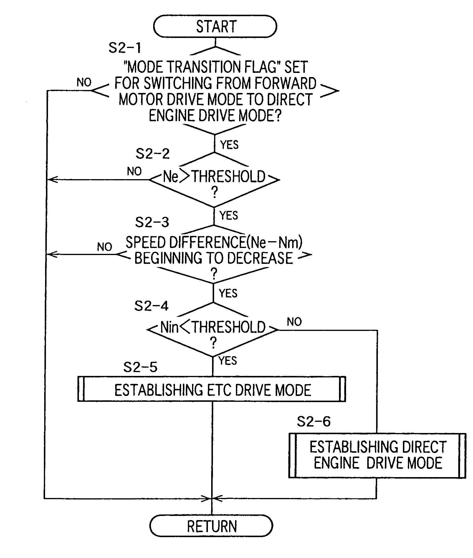
[0111]Referring to the flow chart of FIG. 9, there is illustrated a mode transition control routine which is executed by the hybrid drive control device 60 according to this invention, when the vehicle drive mode is required to be switched from the FORWARD MOTOR DRIVE mode (established by the FORWARD-MOTOR-DRIVE control means 104) to the DIRECT ENGINE DRIVE mode (established by the DIRECT-ENGINE-DRIVE control means 102) or the ETC DRIVE mode (established by the ETC-DRIVE control means 100), upon depression of the accelerator pedal 30 in the FORWARD MOTOR DRIVE mode with the shift lever 30 placed in the operating position D or B. In this case, the DIRECT ENGINE DRIVE mode or the ETC DRIVE mode is established to use the engine 14 for driving the vehicle immediately after the vehicle has been started. The time chart of FIG. 10 indicates changes of the engine and motor speeds Ne, Nm and the operating amount θ ac of the accelerator pedal 78.

[0112]The mode transition control routine of FI...

third embodiment

[0127]In the present third embodiment of FIG. 12, step S3-6 is implemented to determine whether the engine speed Ne is higher than the predetermined threshold, when the switching of the vehicle drive mode from the FORWARD MOTOR DRIVE mode (established by the FORWARD-MOTOR-DRIVE control means 104) to the forward engine drive mode (established by the FORWARD-ENGINE-DRIVE control means 112) is required. When the engine speed Ne is higher than the threshold, the engine 14 is started by merely controlling the fuel injection amount and other suitable parameters for starting of the engine 14, and without cranking of the engine 14 by the starter motor 70. This arrangement permits a rapid and smooth transition of the vehicle drive mode from the FORWARD MOTOR DRIVE mode to the forward engine drive mode upon depression of the accelerator pedal 78 immediately after the vehicle drive mode has been changed from the forward engine drive mode to the FORWARD MOTOR DRIVE mode, as indicated in FIG. 14...


PUM


Abstract

A hybrid vehicle drive system including (a) an engine, (b) an electric motor, (c) a planetary gear device having a first rotary element connected to the engine, a second rotary element connected to the electric motor and connected through a first clutch to an output member connected to vehicle drive wheel, and a third rotary element connected through a second clutch to the output member, (d) a forward-motor-drive control device for engaging the first clutch and releasing the second clutch to thereby establish a forward motor drive mode in which the vehicle is driven in a forward direction by the electric motor, (e) a forward-engine-drive control device for engaging at least the second clutch to establish an engine-drive mode in which the vehicle is driven in the forward direction by the engine, and (f) a second-clutch control device operable upon switching of a vehicle drive mode from the forward motor drive mode to the forward engine drive mode, for engaging the second clutch only after the engine speed has exceeded the motor speed.

Description

[0001]This is a division of application Ser. No. 09 / 684,422 filed 6 Oct. 2000 now U.S. Pat. No. 6,655,485, the content of which is incorporated herein by reference in its entirety.[0002]This application is based on Japanese Patent Application No. 11-288034 filed October 8, the contents of which are incorporated hereinto by reference.BACKGROUND OF THE INVENTION[0003]1. Field of the Invention[0004]The present invention relates in general to a hybrid-vehicle drive system, particularly to a hybrid-vehicle drive system having an engine and an electric motor which are mechanically connected to each other by a planetary gear device, and more particularly to a control when the vehicle drive mode is switched from a motor-drive mode to an engine-drive mode.[0005]2. Discussion of Related Art[0006]There is known a drive system for a hybrid automotive vehicle, which includes (a) an engine operated by combustion of a fuel to produce a drive force, (b) an electric motor, (c) an output member opera...

Claims


Application Information

Patent Timeline
Patent Type & Authority Patents(United States)
IPC IPC(8): B60K6/00B60K17/04B60K1/02B60K6/20B60K6/365B60K6/387B60K6/445B60K6/48B60K6/543B60L50/15B60L50/16B60W10/02B60W10/04B60W10/06B60W10/08B60W10/10B60W10/105B60W10/12B60W20/00F02D29/00F02D29/02F02N11/04F16D48/02F16H3/72F16H9/18F16H61/66
CPCB60W20/40B60K6/387B60K6/48B60K6/543B60L11/123B60W10/02B60W10/06B60W10/08B60W10/10B60W20/00B60W10/107B60K6/365B60K1/02B60L2260/26B60W2710/025F16D2500/1066F16H3/725F16H9/18F16H61/66Y02T10/6217Y02T10/6221Y02T10/6286Y02T10/7077Y10S903/903Y10S903/905Y10S903/946Y10S903/91Y10S903/918B60W2510/0638B60L50/61Y02T10/62Y02T10/70B60K2006/268Y02T10/7072
Inventor ITO, MASATOSHIOBA, HIDEHIROENDO, HIROATSUHOSHIYA, KAZUMI
Owner TOYOTA JIDOSHA KK
Why Eureka
Try Eureka