Dual bridge matrix converter

a converter and matrix technology, applied in the field of ac to ac electrical power converters, can solve the problems of insufficient adoption of matrix converters, inability to achieve the effect of reducing or eliminating high voltage spikes, low rated, and low cos

Active Publication Date: 2006-02-07
WISCONSIN ALUMNI RES FOUND
View PDF11 Cites 109 Cited by
  • Summary
  • Abstract
  • Description
  • Claims
  • Application Information

AI Technical Summary

Benefits of technology

[0005]In accordance with the invention, a dual bridge matrix converter has an input (line-side) converter with controllable switches that receives AC power and provides unidirectional power to high and low DC link lines, and a full bridge output (load-side) converter which receives the power from the DC link lines and provides AC power to output lines. For three-phase operation, the input converter preferably has three switches, each of which is connected by two diodes to one of the input lines and by diodes to the DC link lines, and the output converter has six switches, a pair for each phase leg, which are controlled to provide PWM output waveforms on output lines connected to junctions between each of the pairs of switches. A DC link clamp having a series connected diode and capacitor is connected across the DC link lines. Any negative DC link current flows into the clamp capacitor through the clamp diode for a short period of time to reduce or eliminate high voltage spikes. Because the clamp capacitor is not required to store large amounts of energy to supply the output inverter (as is required in conventional AC to DC to AC converters), the clamp capacitor can be relatively small, inexpensive, and low rated. The DC link clamp may also include an additional switch connected in parallel with the clamp diode to allow exchange of power between the clamp capacitor and the output converter, allowing operation under low power factor conditions.

Problems solved by technology

However, the matrix converter has not been widely adopted.
One reason is that the conventional modulation algorithm for such converters requires an involved and difficult pulse width modulation (PWM) switching strategy.
However, a disadvantage of this converter configuration is that its DC link current must be non-negative to guarantee safe operation.
If the DC link current becomes negative, some high voltage spikes can be generated because there are no reverse current paths in the line-side converter, and the converter may be damaged by these spikes.

Method used


Image

  • Dual bridge matrix converter
  • Dual bridge matrix converter
  • Dual bridge matrix converter

Examples


Embodiment Construction

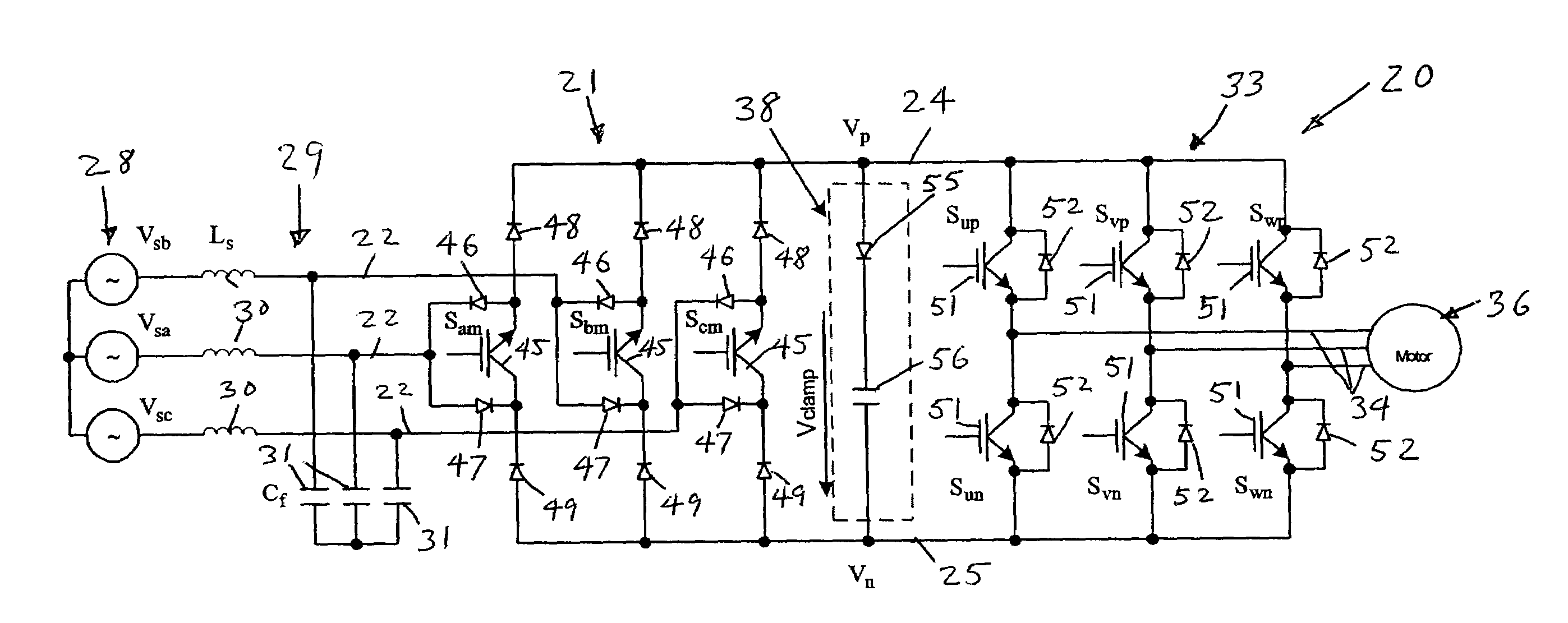
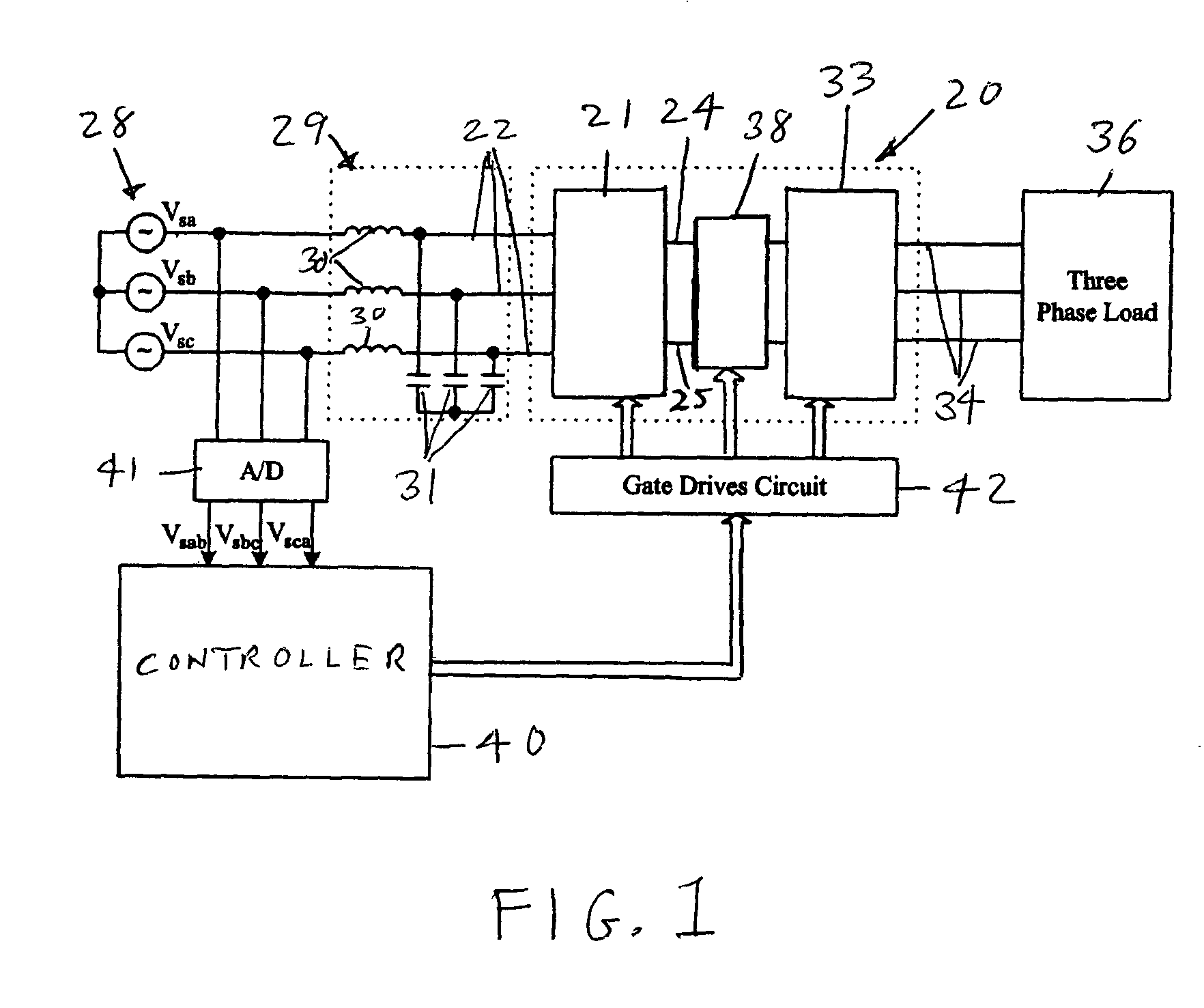
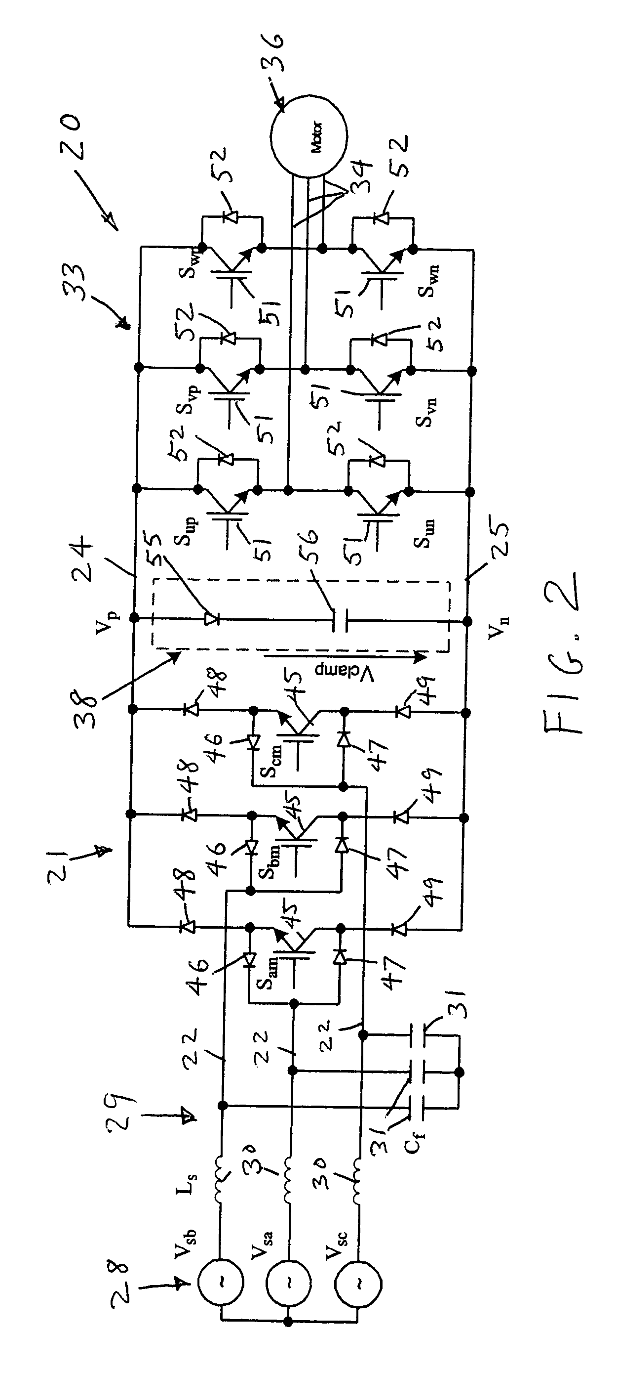
[0021]With reference to the drawings, a dual bridge matrix converter with a DC link clamp in accordance with the invention is shown in schematic form generally at 20 in FIG. 1. The converter 20 includes an input or line-side converter 21 which receives AC input power on input lines 22 (three-phase lines shown for illustration). The line-side converter is connected across and provides unidirectional power to a DC link composed of a high DC link line 24 and a low DC link line 25. The line-side converter 21 may be any of various circuit topologies which may be used without a DC link energy storage capacitor, for example, 18, 15, 12 and 9 switch topologies. The AC power from an AC power system 28 is preferably filtered by an input filter 29 which may be comprised of series inductors 30 and parallel connected capacitors 31. The dual bridge matrix converter 20 also includes an output or load-side converter 33 which is connected across the DC link lines 24 and 25 to receive power therefrom...


PUM


Abstract

A dual bridge matrix converter has a line-side converter with controllable switches that receives AC power and provides unidirectional power to high and low DC link lines, and a load-side converter which receives the power from the DC link lines and provides AC power to output lines. A clamp circuit is connected across the DC link lines and includes a series connected diode and a capacitor. Negative DC link current will be conducted through the clamp diode to charge the clamp capacitor to avoid voltage spikes on the DC link lines. A controllable switch may be connected in parallel with the clamp diode and is turned on when the voltage across the clamp capacitor is above a threshold that is greater than the normal peak-to-peak AC input voltage. The switch is turned off when the voltage across the clamp capacitor is lower than the threshold voltage.

Description

REFERENCE TO GOVERNMENT RIGHTS[0001]This invention was made with United States government support awarded by the following agency: NSF 9731677. The United States government has certain rights in this invention.FIELD OF THE INVENTION[0002]This invention pertains generally to AC to AC electrical power converters and particularly to dual bridge matrix converters.BACKGROUND OF THE INVENTION[0003]A variety of circuit topologies have been developed using solid-state switches for conversion of AC power at one frequency to AC power at another frequency. Among the many circuit designs are conventional AC to DC to AC converters, in which the AC power is rectified to a DC voltage applied across DC bus lines and the DC voltage is then converted to AC by an inverter, and matrix converters, in which the input AC power is not rectified but is directly converted using a matrix of bidirectional switching elements (conventionally formed of pairs of transistors). The main advantages of matrix converte...

Claims


Application Information

Patent Timeline
Patent Type & Authority Patents(United States)
IPC IPC(8): H02M5/40H02M1/14H02J3/00H02M5/458
CPCH02M5/4585
Inventor WEI, LIXIANGLIPO, THOMAS A.
Owner WISCONSIN ALUMNI RES FOUND
Why Eureka
Try Eureka