Internal combustion engine and method of operating internal combustion engine

a technology of internal combustion engine and combustion engine, which is applied in the direction of combustion air/fuel air treatment, electric control, machines/engines, etc., can solve the problems of difficult operation of internal combustion engine and easy production of reformed gas

Inactive Publication Date: 2006-02-14
TOYOTA JIDOSHA KK
View PDF23 Cites 56 Cited by
  • Summary
  • Abstract
  • Description
  • Claims
  • Application Information

AI Technical Summary

Benefits of technology

[0012]That is, the reforming efficiency of the reformer changes in accordance with the air-fuel ratio of the mixture in the reformer. However, if the air-fuel ratio of the mixture in the reformer is held within a predetermined range, the reforming efficiency of the reformer is also held within a predetermined period. In view of this, according to this internal combustion engine, the control portion sets the air-fuel ratio of the mixture in the reformer within a predetermined range (preferably as a constant value) such that the reforming efficiency of the reformer is held within a desired range, and sets the amount of the mixture supplied to the reformer such that an actual output torque of the internal combustion engine coincides with a target torque. Thereby, the ratio among the fuel components contained in the reformed gas produced by the reformer can be grasped accurately. This construction makes it possible to supply a desired reformed gas from the reformer to the combustion chamber, and to thereby cause the internal combustion engine to operate precisely in conformity with a required condition.
[0044]The method of operation of the aforementioned aspect makes it possible to supply a desired reformed gas from the reformer to the combustion chamber and to cause the internal combustion engine to operate precisely in conformity with a required condition.

Problems solved by technology

However, when an internal combustion engine equipped with a reformer is viewed as a whole, suitable management of the temperature of the reformer alone does not make it easy to produce a reformed gas for causing the internal combustion engine to operate in conformity with a required condition.

Method used


Image

  • Internal combustion engine and method of operating internal combustion engine
  • Internal combustion engine and method of operating internal combustion engine
  • Internal combustion engine and method of operating internal combustion engine

Examples


first embodiment

[0074][First Embodiment]

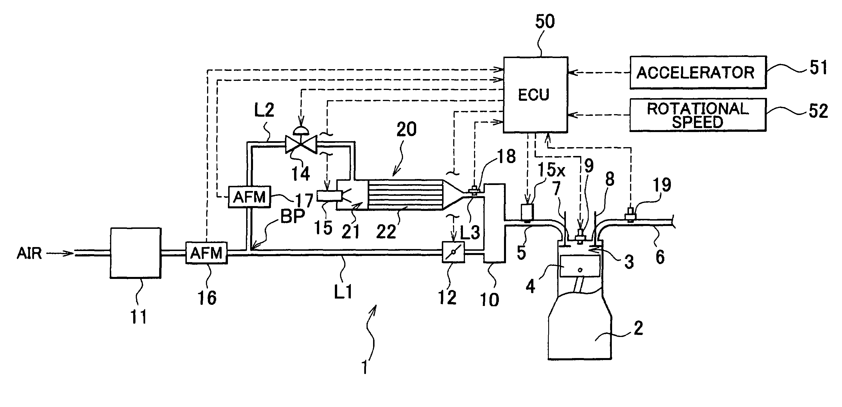
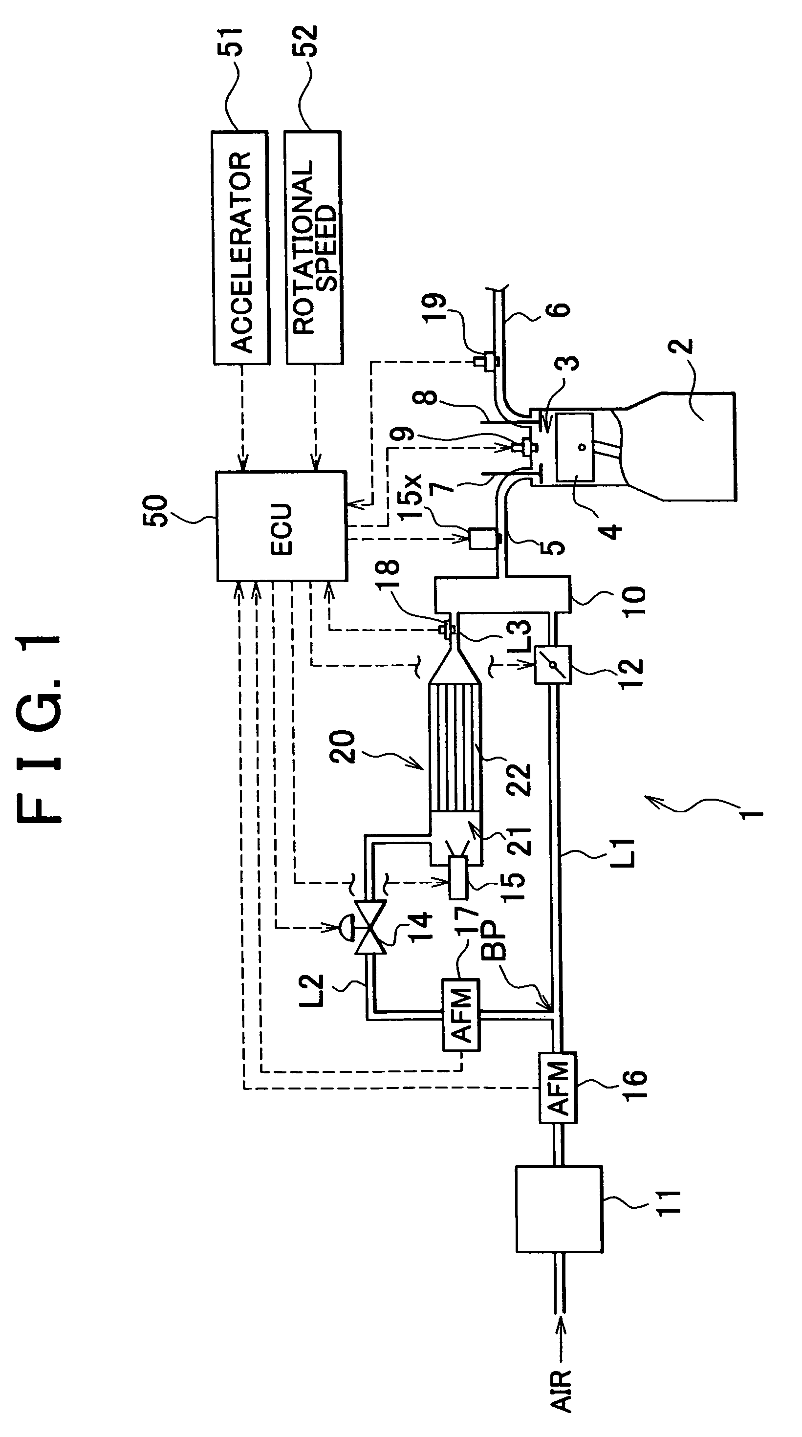
[0075]FIG. 1 is a schematic diagram of an internal combustion engine in accordance with the first embodiment of the invention. An internal combustion engine 1 shown in FIG. 1 generates power by burning a mixture containing fuel components in a plurality of combustion chambers 3 formed in an engine block 2 and reciprocating pistons 4 in the combustion chambers 3. An intake pipe 5 and an exhaust pipe 6 are connected to each of the combustion chambers 3. Each intake port is provided with an intake valve 7, while each exhaust port is provided with an exhaust valve 8. The internal combustion engine 1 has an ignition plug 9 for each of the combustion chambers 3.

[0076]As shown in FIG. 1, the intake pipe 5 is connected to a surge tank 10 to which an air-supply pipe L1 is connected. The air-supply pipe L1 is connected to an air intake (not shown) via an air cleaner 11. The air-supply pipe L1 extends across an electronic throttle 12 (which is located between the surge ...

second embodiment

[0095][Second Embodiment]

[0096]Hereinafter, an internal combustion engine in accordance with the second embodiment of the invention will be described with reference to FIGS. 10 to 21. Components identical with those described in relation to the aforementioned first embodiment are denoted by the same reference numerals, and repetition of the same description will be avoided.

[0097]An internal combustion engine 1A shown in FIG. 10 is basically identical in construction with the internal combustion engine 1 in accordance with the aforementioned first embodiment. In the internal combustion engine 1A in accordance with the second embodiment, however, the air flow meter disposed upstream of the reformer 20 is removed from the bypass pipe L2 with a view to lowering the cost of the engine as a whole and reducing the volume of a required space. In the internal combustion engine 1A, a pre-heater 23 such as an electric heater or the like is disposed at an upstream end portion of the reforming r...

third embodiment

[0138](Third Embodiment)

[0139]Hereinafter, an internal combustion engine in accordance with the third embodiment of the invention will be described with reference to FIGS. 22 and 23. Components identical with those described in relation to the aforementioned first embodiment are denoted by the same reference numerals, and repetition of the same description will be avoided.

[0140]An internal combustion engine 1B shown in FIG. 22 is basically identical in construction with the internal combustion engine 1A in accordance with the aforementioned second embodiment. The internal combustion engine 1B in accordance with the third embodiment is constructed such that exhaust gas (inactive gas) flowing from the combustion chambers 3 can be recirculated to the reformer 20. That is, an exhaust gas recirculation pipe L4 branches off from the exhaust pipe 6 connected to each of the combustion chambers 3 at a position downstream of the exhaust gas A / F sensor 19. A flow rate adjusting valve 14B exten...


PUM

PropertyMeasurementUnit
temperatureaaaaaaaaaa
torqueaaaaaaaaaa

Abstract

An internal combustion engine in accordance with one aspect of the invention is characterized by comprising a combustion chamber, a reformer, and a control portion. A predetermined fuel component is burnt in the combustion chamber. The reformer has a reforming catalyst, and that produces a reformed gas which contains the fuel component obtained by reforming a mixture of fuel and air and which supplied to the combustion chamber. The control portion sets an air-fuel ratio of the mixture in the reformer such that a reforming efficiency of the reformer is held within a predetermined range, and sets an amount of the mixture supplied to the reformer such that an actual output torque of the internal combustion engine coincides with a target torque.

Description

INCORPORATION BY REFERENCE[0001]The disclosure of Japanese Patent Applications No. 2003-018261 filed on Jan. 28, 2003 and No. 2003-314368 filed on Sep. 5, 2003 including the specifications, drawings and abstracts are incorporated herein by reference in therein entirety.BACKGROUND OF THE INVENTION[0002]1. Field of the Invention[0003]The invention relates to an internal combustion engine and a method of operating an internal combustion engine.[0004]2. Description of the Related Art[0005]There has been known an internal combustion engine that is provided with a reformer including a reforming catalyst and that causes fuel components obtained by reforming various fuels by means of the reformer to burn in combustion chambers with a view to stabilizing combustion and reducing the amounts of HC and NOx contained in exhaust gas (Japanese Patent Application Laid-Open No. 2001-241365).[0006]One known reformer for reforming a hydrocarbon fuel such as methanol or the like is designed to produce ...

Claims


Application Information

Patent Timeline
Patent Type & Authority Patents(United States)
IPC IPC(8): F02B43/08C01B3/38F02D21/08F02D41/02F02D41/04F02D45/00F02M23/10F02M27/02
CPCF02M23/10F02M27/02F02M25/12Y02T10/146Y02T10/12
Inventor WAKAO, KAZUHIROSAKURAI, KAZUHIROITOU, TAKAAKIICHINOSE, HIROKI
Owner TOYOTA JIDOSHA KK
Why Eureka
Try Eureka