

Sensor dispensing device
a technology for dispensing devices and sensors, which is applied in the direction of instruments, apparatus for dispensing discrete objects, de-stacking articles, etc., can solve the problems of reducing shelf life and limited shelf li
- Summary
- Abstract
- Description
- Claims
- Application Information
AI Technical Summary
Benefits of technology
Problems solved by technology
Method used
Image

Examples
second embodiment
[0065]Referring now to FIGS. 3 to 6, the invention is described. The actuating sleeve 4 is mounted either side of the upper 22 and lower 46 meter casings. The sleeve 4 accommodates left and right handed users and allows various gripping strategies. The meter casing 22, in this example formed from an acrylic material, is provided with a front-mounted LCD 6, key-pad function buttons 20, and strip ejection slot 24. The LCD key-pad, and other meter electronics components are mounted on a main PCB 42 which is in turn connected to a second PCB 30. The second PCB 30 is electrically connected to a contact block 28, with which the electrodes of the test strip 8 engage when the strip is in the engagement location, as best shown in FIG. 17.
[0066]Cartridge access from the side of the device is provided by a cartridge cover 44 which is opened by operation of a release button 26. In this example the cartridge cover 44 provides access to batteries 38 in addition to the cartridge assembly 32. The b...
third embodiment
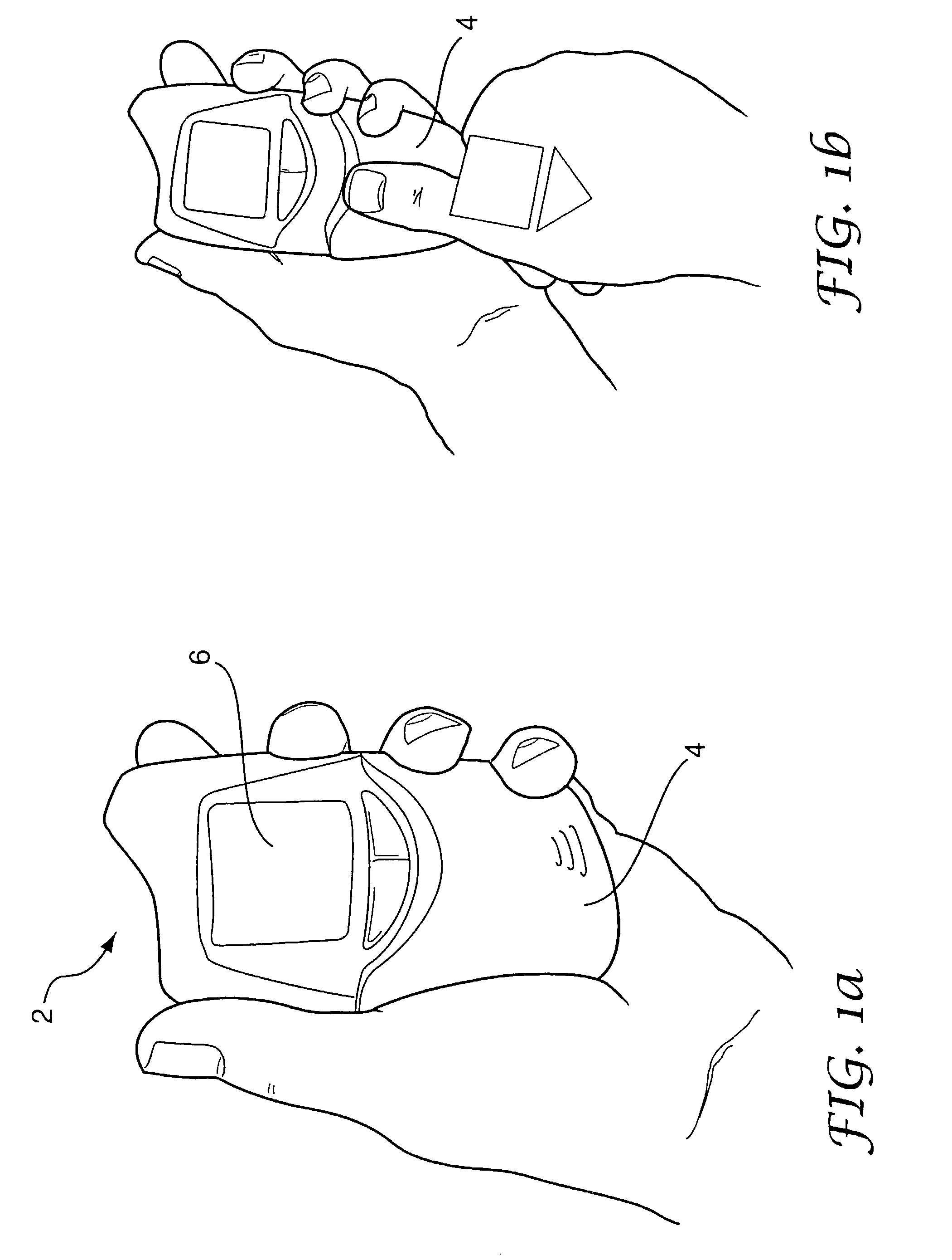
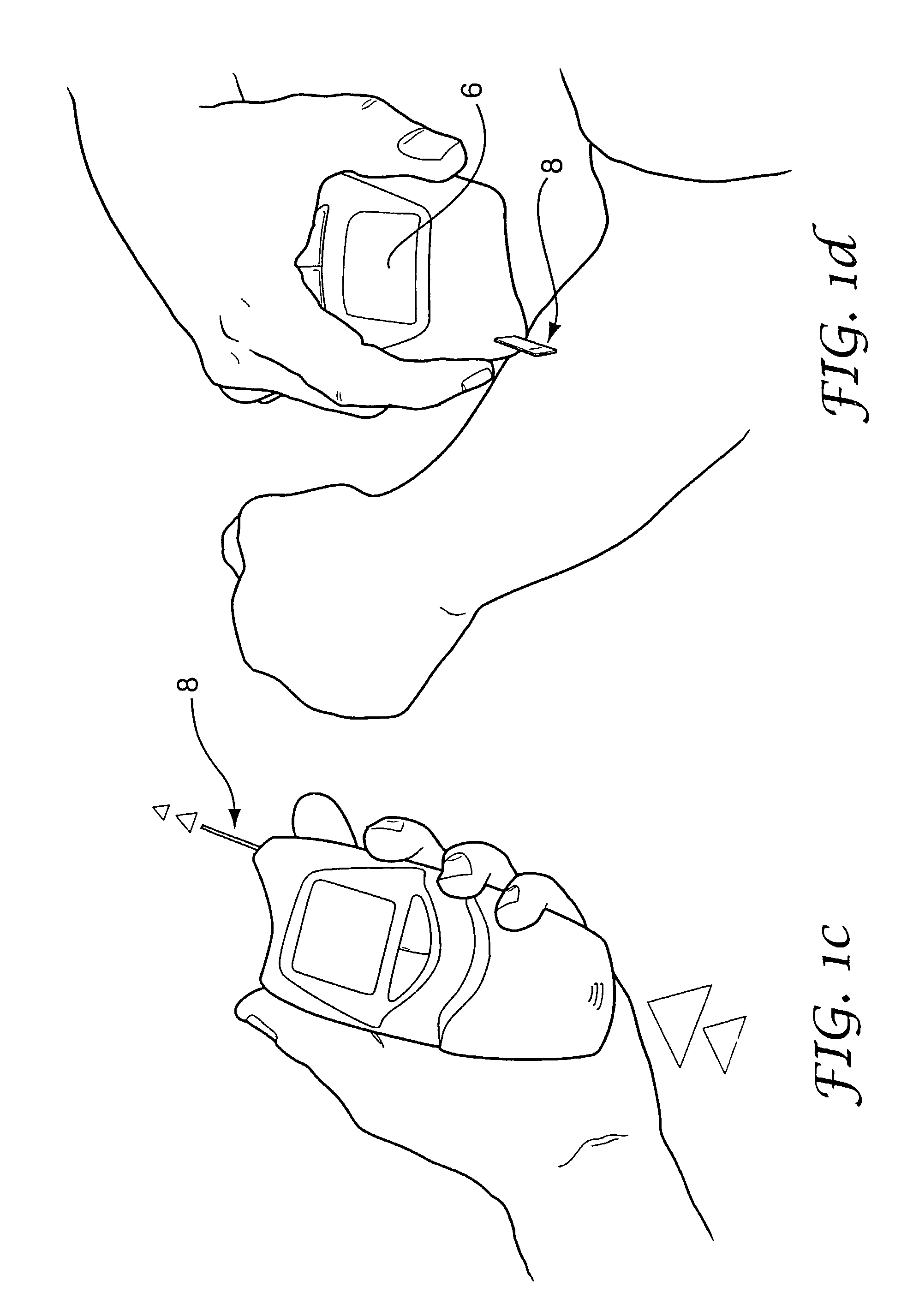
[0067]the invention is illustrated with reference to FIGS. 7 to 10. In this embodiment the LCD 6 is side-mounted to maximise the gripping area without obscuring the screen. This arrangement facilitates holding the device with a precision pen-style grip as well as in a fist. The strip ejection point 24 is situated at an edge projection, which helps to indicate to the user where the strip will emerge from. A separate battery cover 54 is provided, which has a battery contact member 52 provided on its inner surface. As illustrated in FIG. 9, the actuator rack 36 engages with the smaller wheel of a pinion gear 56, while the strip-pusher rack 34 is driven by the larger wheel of the pinion gear.
fourth embodiment
[0068]the device is shown in FIGS. 11 and 12, which employs an alternative mechanism for driving the slider 18. Here, the sleeve (not shown) is directly connected to an actuating plate 60 which has an arcuate slot 62 therein. The slider 18 is provided with a projection that sits in a slot at one end of a pivot arm 58. The arrangement is such that turning of the pivot arm 58 produces linear translation of the slider 58 by virtue of lost motion in the slot. The pivot arm 58 is provided with a projection or pin 64 which is disposed in the arcuate slot 62 so that sliding of the actuating plate 60 causes pivoting of the pivot arm 58 and hence sliding of the slider 18. Referring to FIG. 12, it will be seen that sliding the actuating plate 60 from the upper position (shown in white) to the lower position (shaded) causes the slider 18 to move from the rest position shown on the extreme right, to the position shown on the extreme left. Reversal of this movement, for example by means of a spr...
PUM
 Abstract
Description
Claims
Application Information