Channel for transport of electron beam from accelerator to irradiated product

a technology of electron beam and accelerator, which is applied in the direction of irradiation devices, nuclear engineering, therapy, etc., can solve the problems of reducing the value of absorbed dose in the irradiated product, reducing the penetration of e-beam into the product, and certain products giving off gases, so as to facilitate the use of lower-energy e-beams, facilitate the irradiation process, and facilitate the effect of absorbing dose distribution

Inactive Publication Date: 2006-02-14
STERIS CORP
View PDF10 Cites 6 Cited by
  • Summary
  • Abstract
  • Description
  • Claims
  • Application Information

AI Technical Summary

Benefits of technology

[0018]An advantage of the present invention is a method and apparatus for the transport of an e-beam for irradiating articles.
[0019]Another advantage of the present invention is a method and apparatus as described above that increases the efficiency of the irradiation process.
[0020]Another advantage of the present invention is a method and apparatus as described above that facilitates using lower-energy e-beams to irradiate the articles.
[0021]A still further advantage of the present invention is a method and apparatus as described above that facilitates a more homogeneous distribution of absorbed doses in the irradiated article.
[0022]A still further advantage of the present invention is a method and apparatus as described above that is adjustable to irradiate objects of different dimensions.
[0023]These and other objects will become apparent from the following description of a preferred embodiment taken together with the accompanying drawings and the appended claims.

Problems solved by technology

First, there is a decrease in the value of absorbed dose in the irradiated product.
Second, the angle of incidence of the scanning electron beam on the product decreases the penetration of the e-beam into the product.
A still further problem with irradiating products in air is that certain products give off gases that accumulate at the surface of the product during irradiation.
This accumulation of gases leads to uncontrolled variation of the parameters of the air plasma.
The propagation of this type of e-beam in air has the same problems with non-stability as described above.
An additional problem is that the variation of current density tends to lead to a variation of dose distribution in an irradiated product.

Method used


Image

  • Channel for transport of electron beam from accelerator to irradiated product
  • Channel for transport of electron beam from accelerator to irradiated product
  • Channel for transport of electron beam from accelerator to irradiated product

Examples


Embodiment Construction

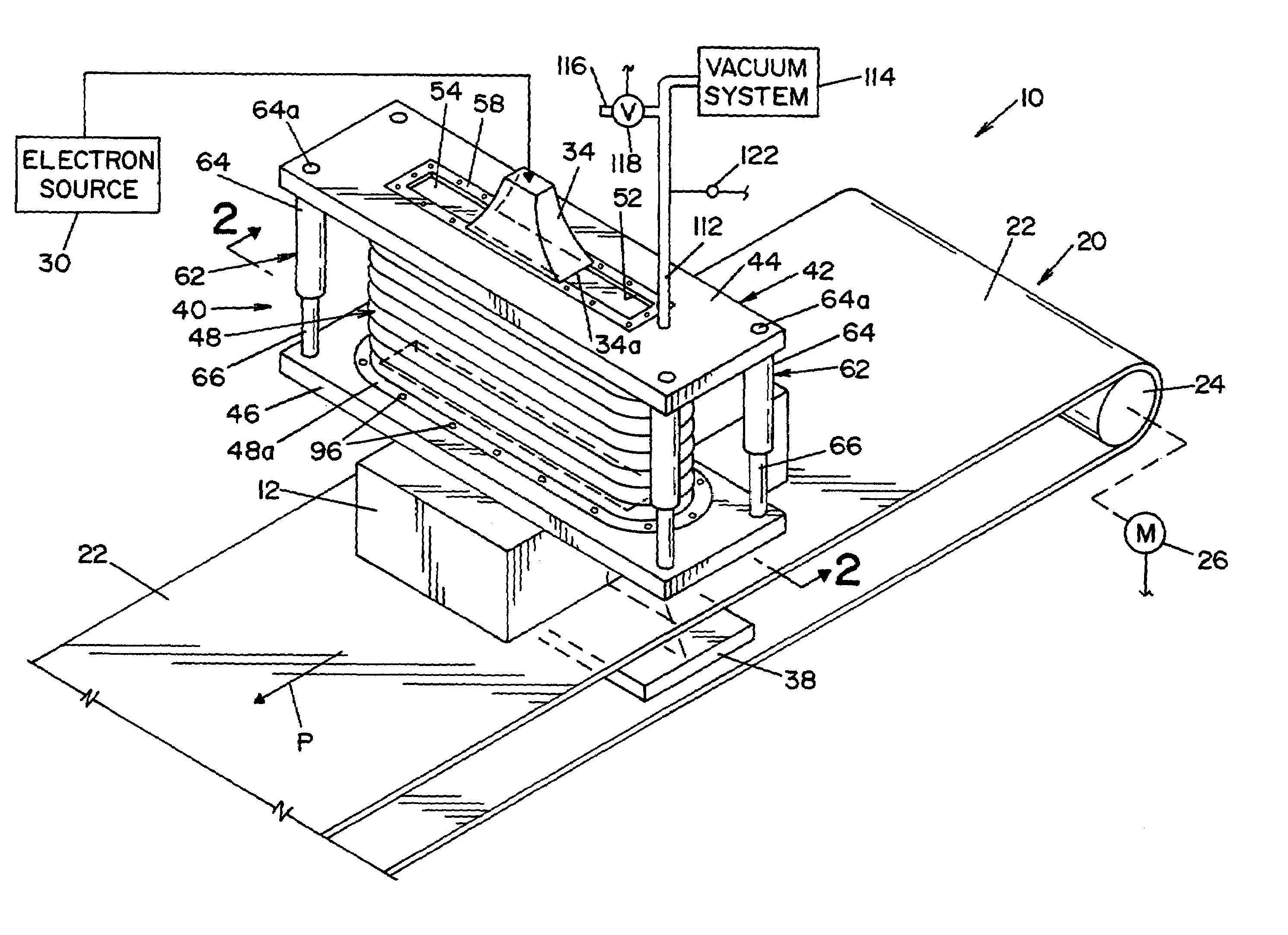
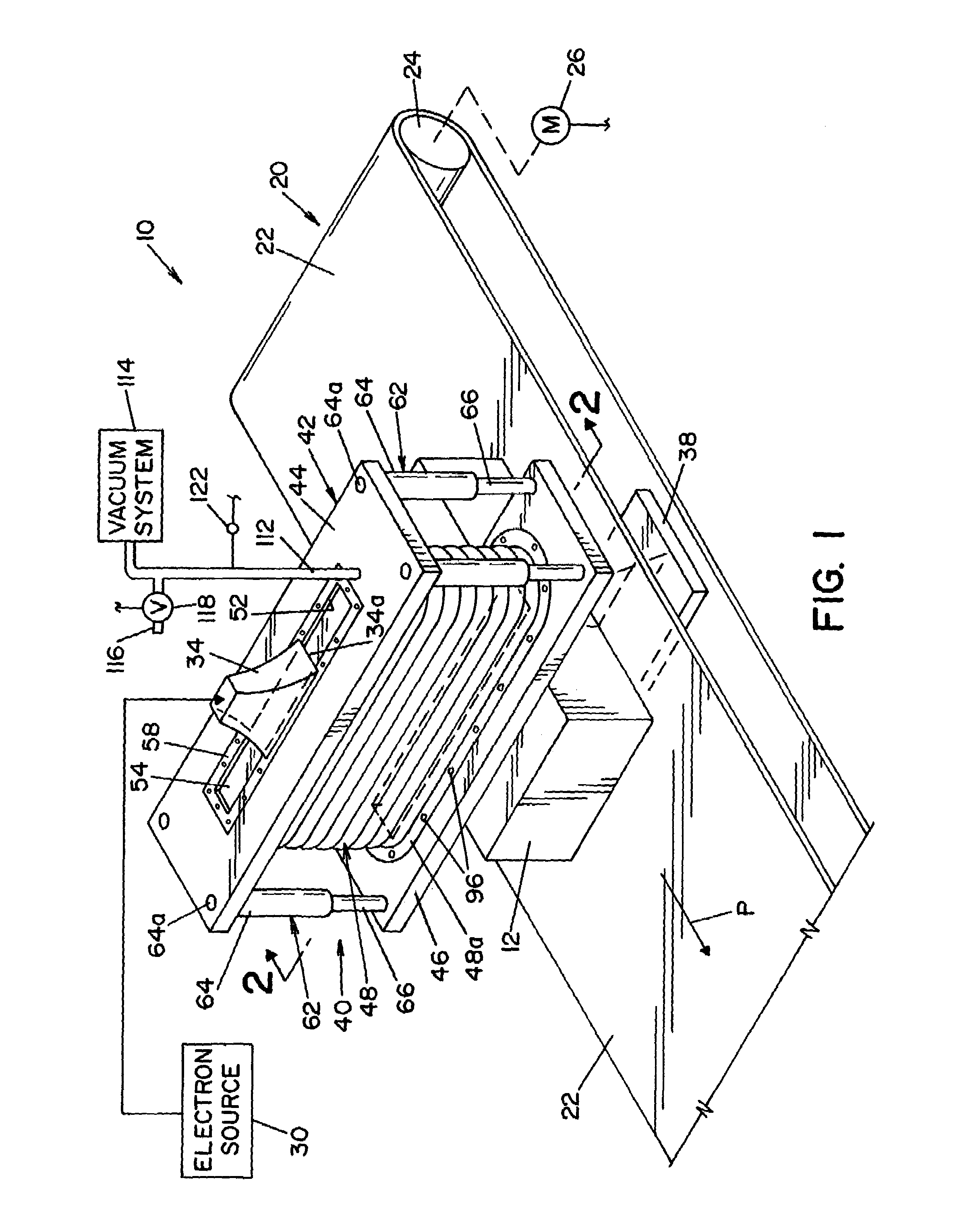
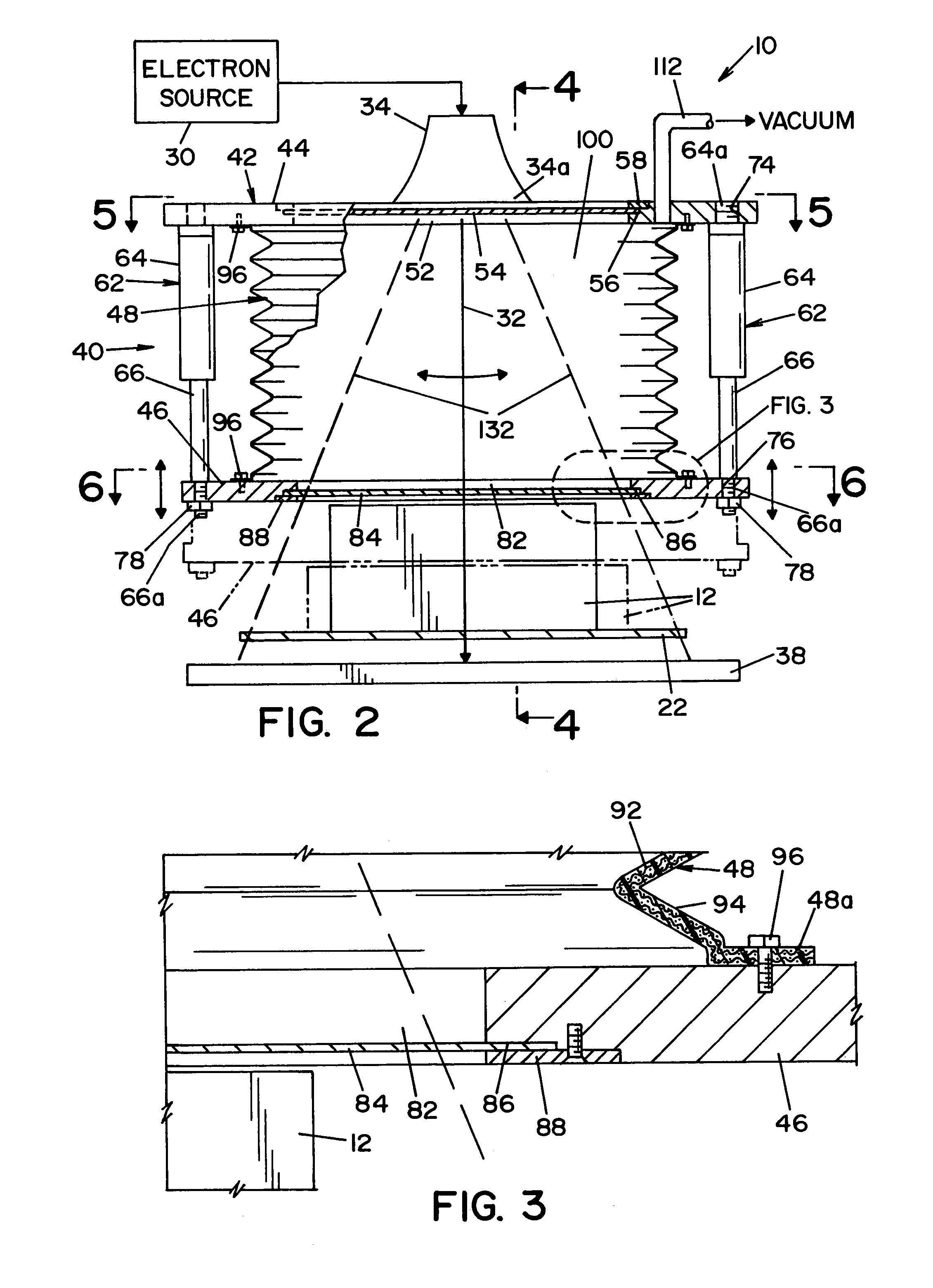
[0033]Referring now to the drawings wherein the showings are for the purpose of illustrating a preferred embodiment of the invention only and not for the purposes of limiting the same, FIG. 1 shows a process 10 for irradiating products or objects 12. The object 12 to be irradiated is shown moving along a conveyor system 20. Conveyor system 20 includes a generally endless conveyor belt 22 that is movable over a pair of rollers 24. (Only one roller is illustrated in the drawing.) One roller 24 is driven by a motor 26 that is schematically illustrated in FIG. 1. An electron accelerator 30, schematically illustrated in FIG. 1, generates an electron beam 32 (best seen in FIG. 2) that is conveyed through a scan horn 34 that scans beam 32 back and forth, in a conventionally known manner. Conveyor system 20 is disposed relative to scan horn 34 such that e-beam 32 from scan horn 34 traverses back and forth across conveyor belt 22. In this respect, any product or object 12 moving along convey...


PUM


Abstract

A device for transport of an electron beam from an accelerator to a product to be irradiated, comprised of a passive plasma channel for forming a low density plasma by ionizing gas molecules in a chamber under low pressure conditions. The device being adjustable in size such that the chamber formed by the device occupies a majority of the distance between the e-beam accelerator and the product to be irradiated.

Description

FIELD OF THE INVENTION[0001]The present invention relates generally to an apparatus for the irradiation of objects and the like, and more particularly to a device for forming a chamber that focuses an electron beam for irradiating a product.BACKGROUND OF THE INVENTION[0002]It is known that the physical properties of a material may be altered by exposing the material to electron (e-beam) radiation. In this respect, manufacturers treat certain products, such as plastic articles or animal feed, to produce a desired alteration in the products. In a conventional product irradiation process, a product is moved along a conveyor through an e-beam that scans across, i.e. traverses, the path of the conveyor. The e-beam is scanned across the conveyor by means of a scan horn that is a fixed distance from the surface of the conveyor. Depending upon the size of the product to be irradiated, the distance between the scan horn and the product may vary.[0003]As the e-beam travels through air from th...

Claims


Application Information

Patent Timeline
Patent Type & Authority Patents(United States)
IPC IPC(8): G21G4/00
CPCG21K5/02
Inventor KORENEV, SERGEY A.
Owner STERIS CORP
Why Eureka
Try Eureka