
Antenna system employing floating ground plane

a floating ground plane and antenna technology, applied in the direction of resonant antennas, substantially flat resonant elements, radiating element structural forms, etc., can solve the problem that the mounting arrangement of vehicles having composite body parts generally has not optimized wireless signal communication, and achieves stable impedance, enhanced antenna performance, and high gain value

Inactive Publication Date: 2006-02-14
DELPHI TECH INC
View PDF4 Cites 42 Cited by
  • Summary
  • Abstract
  • Description
  • Claims
  • Application Information

AI Technical Summary

Benefits of technology

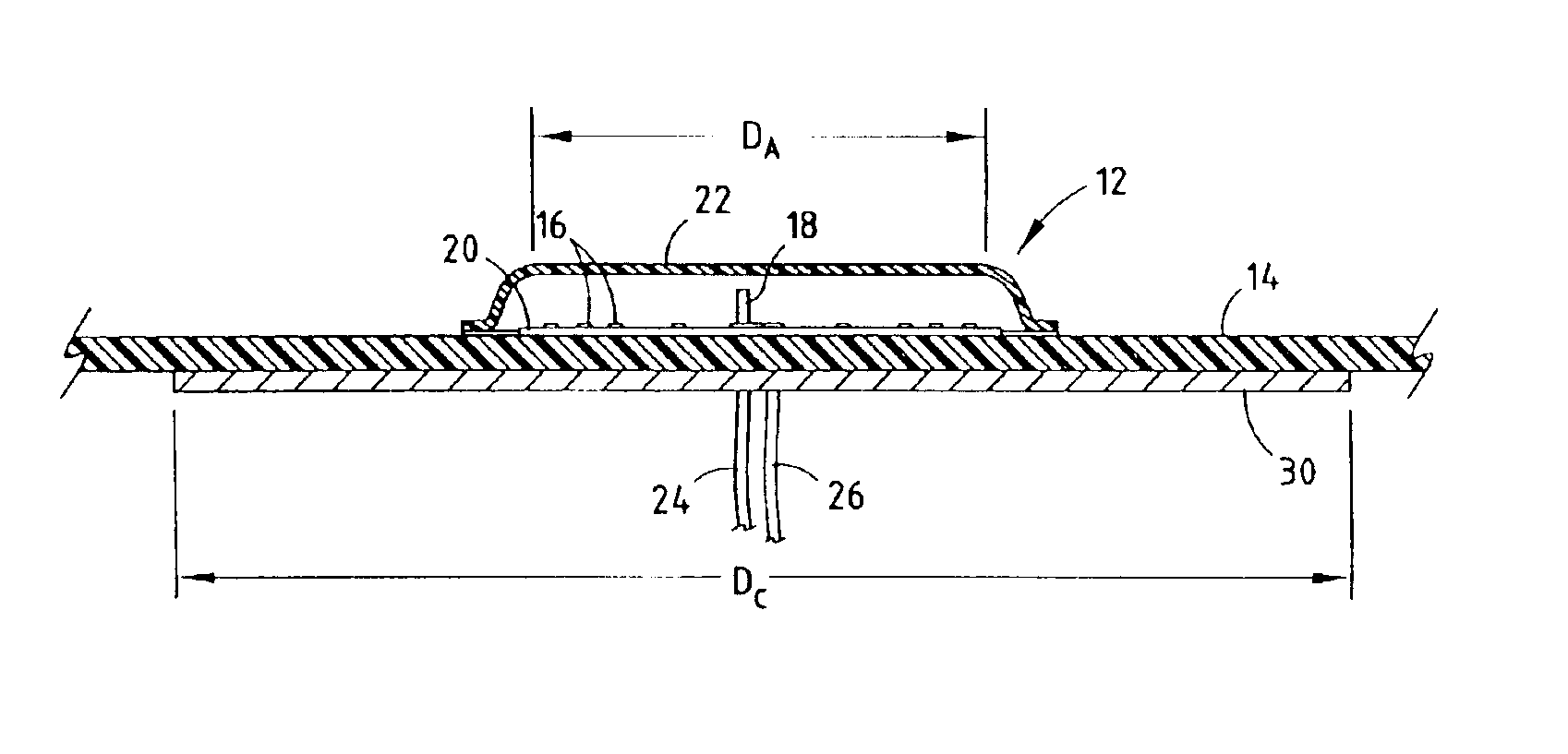
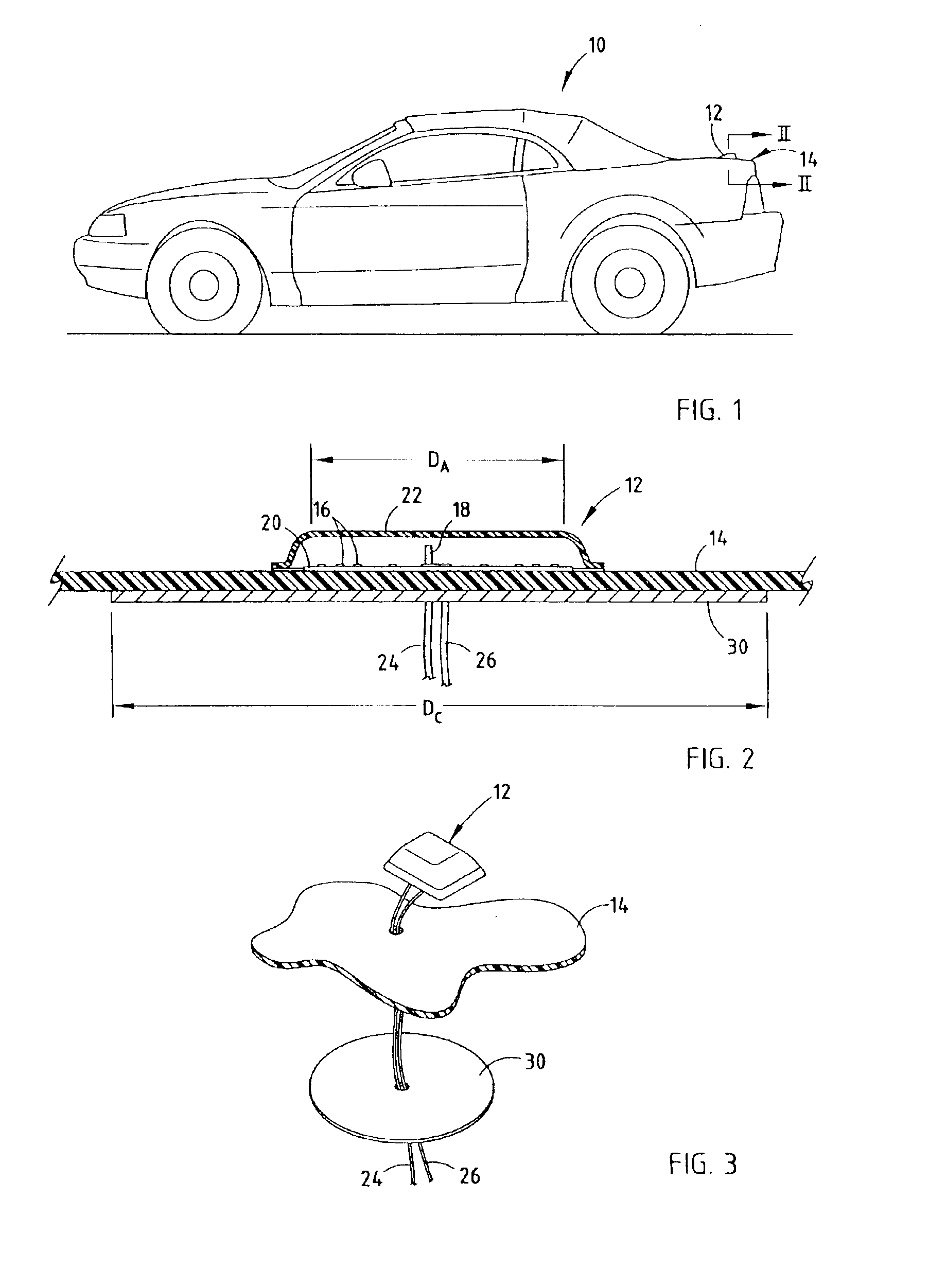
[0005]The present invention provides for an antenna system mounted on an electrically non-conductive dielectric member in a manner to allow for enhanced antenna performance. The antenna system includes a dielectric medium having first and second surfaces and a dielectric thickness between the first and second surfaces. An antenna is mounted to the first surface of the dielectric medium for performing at least one of receiving and transmitting signals. An electrically conductive member is mounted to the second surface of the dielectric medium for forming a capacitive coupling with the antenna. The electrically conductive member is dielectrically isolated from electrical ground. Accordingly, the antenna system of the present invention refines the signal radiation pattern, provides stable impedance, achieves high gain values and low ripple (i.e., maximum / minimum signal ratio), and thus stabilizes the antenna radiation pattern and enhances signal performance.

Problems solved by technology

However, many vehicle body housings are made of a composite dielectric (i.e., electrically non-conductive) material, such as fiberglass.
However, the antenna mount arrangement on vehicles having composite body members generally has not optimized the wireless signal communication.

Method used


Image

  • Antenna system employing floating ground plane
  • Antenna system employing floating ground plane

Examples


Embodiment Construction

[0011]Referring to FIG. 1, an automotive vehicle 10 is generally illustrated having an antenna 12 mounted on top of a rear decklid body panel 14. The vehicle 10 has an outer housing (body) that is generally made up of one or more body panels. At least one body panel (e.g., decklid) 14 is made of an electrically non-conductive (i.e., dielectric) material such as a dielectric composite material. For example, the rear decklid body panel 14 may be composed of fiberglass or other electrically non-conductive composite materials. The antenna 12 is mounted to one of the dielectric body panels, such as rear decklid 14, as shown. However, it should be appreciated that antenna 12 can be mounted on other dielectric body panels at other locations on the vehicle, including the roof, the front hood, and other members which present a suitable mounting arrangement for an antenna to communicate with a remote signal transmitter and / or receiver.

[0012]The antenna 12 is positioned to communicate with a r...


PUM


Abstract

An antenna system is assembled to a dielectric medium on a vehicle and is spaced from an electrically conductive member so as to allow for enhanced antenna performance. The dielectric medium has first and second surfaces and a dielectric thickness between the first and second surfaces. An antenna is mounted to the first surface of the dielectric medium for receiving and / or transmitting signals. An electrically conductive member is mounted to the second surface of the dielectric medium for providing a floating ground that forms a capacitive coupling with the antenna. The electrically conductive member is dielectrically isolated from vehicle electrical ground.

Description

TECHNICAL FIELD[0001]The present invention generally relates to antennas and, more particularly, to a mounted antenna system employing a ground plane, particularly for use on a vehicle.BACKGROUND OF THE INVENTION[0002]Automotive vehicles are increasingly being equipped with electronic devices such as radios, global positioning system (GPS) receivers, cell phones, and other infotainment, entertainment and telematics devices that require wireless data communication. Each wireless communication device typically employs an antenna to receive and / or transmit signals to communicate with remote transmitting and / or receiving devices. For example Satellite Digital Audio Radio System (SDARS) antennas communicate radio frequency (RF) signals with one or more satellites. The SDARS antennas are generally required to be positioned in a substantially unobstructed view of one or more satellites to communicate signals therebetween.[0003]In conventional vehicle mounted antenna applications, antennas ...

Claims


Application Information

Patent Timeline
IPC IPC(8): H01Q1/32H01Q1/38H01Q9/04
CPCH01Q1/3275H01Q9/0407H01Q1/38
Inventor PAKRAY, AHMAD B.LEE, KENNETH P.ZAFAR, IMTIAZ
Owner DELPHI TECH INC
Learn More