Controller circuit supplying energy to a display device

a controller circuit and display device technology, applied in the direction of dc-ac conversion without reversal, process and machine control, instruments, etc., can solve the problems of large ripple on the power line, increase the size of the circuit, and degrade the signal/noise integrity of the system, so as to reduce the ripple effect of the power line, reduce the cost, and reduce the effect of programmable and simplified circuits

Inactive Publication Date: 2006-02-14
O2 MICRO INT LTD
View PDF4 Cites 36 Cited by
  • Summary
  • Abstract
  • Description
  • Claims
  • Application Information

AI Technical Summary

Benefits of technology

[0009]It is an object of the present invention to provide a simpler controller of a simpler phase shift circuit technique, wherein a simpler user-programmable number of phases according to the number of inverters is used, such that a high power, low cost and smaller multiple-inverter system can be achieved.
[0010]It is another object of the present invention to provide an improved electrical circuit comprising multiple power circuits, such as DC / AC inverters, for driving multiple loads, such as CCFL loads, which reduces instantaneous high current ripples and noises caused by turning ON and turning OFF switches in the power circuits simultaneously.
[0012]It is yet another object of the present invention to provide a method for driving an electrical circuit comprising multiple power circuits, such as DC / AC inverters, for driving multiple loads, such as CCFL loads, which reduces instantaneous high current ripples and noises caused by turning ON and turning OFF switches in the power circuits simultaneously.
[0014]In addition, the electrical circuit in accordance with the present invention provides a phase shift of the switching ON / OFF between DC / AC inverters for driving CCFL loads, wherein the number of phase shifts is programmed in accordance with the number of DC / AC inverters connected. According to the present invention, a first DC / AC inverter receives a first pulse signal from the pulse generator and a reference signal from the phase selector indicating the number of phases and generates a second pulse signal to a second DC / AC inverter. The second DC / AC inverter receives the second pulse signal having a phase shift with respect to the first pulse signal input to the first DC / AC inverter. Likewise, the second DC / AC inverter generates a third pulse signal to a third DC / AC inverter having the same amount of phase shift with respect to the second pulse signal input to the second DC / AC inverter, whereby all DC / AC inverters are turned on and turned off with equal phase shift between the adjacent inverters. According to the present invention, the ripple on the power line is thus effectively reduced, the circuit is programmable and simplified and the cost is reduced.

Problems solved by technology

Therefore, there is a large ripple on the power line.
The simultaneous turning on and off at all inverters cause noises on the power line which degrades the signal / noise integrity in the system.
However, the disadvantage is that the size of the circuit is increased, which in turn increases the system cost.
However, the problem is that the controller (40) is fixed to the number of original demanded loads, in other words, the number of CCFL loads equals to the lines which deliver phase shifts from the controller (40) to each inverter (10, 12, 14, .
Another disadvantage is that the controller (40) needs to generate a high-frequency clock signal having a frequency of N times the operating frequency of the individual DC / AC inverter.

Method used


Image

  • Controller circuit supplying energy to a display device
  • Controller circuit supplying energy to a display device
  • Controller circuit supplying energy to a display device

Examples


Embodiment Construction

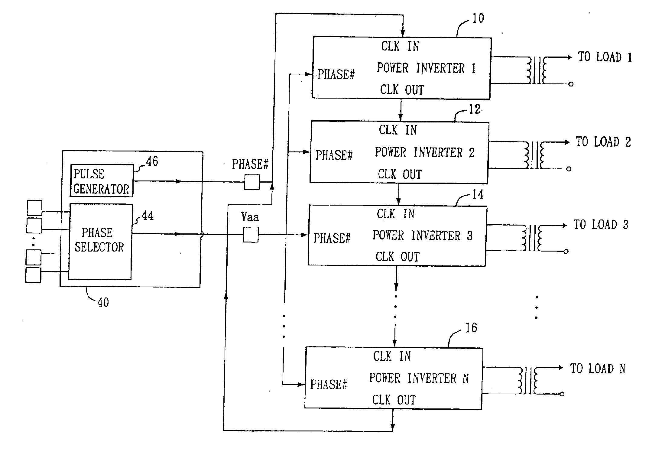
[0028]FIG. 3 is a block diagram of the electrical circuit in accordance with the present invention used for driving multiple loads, such as light source loads or CCFL loads. The electrical circuit comprises a controller (40) and at least two power circuits (10,12), such as DC / AC inverters. The controller (40) comprises a selector (44), such as a phase selector, and a pulse generator (46), such as an oscillator.

[0029]The selector (44) generates a reference signal according to variable input signals and the reference signal is coupled to the at least two power circuits (10,12) for indicating a number of power circuits controlled or a number of phases to be shifted. That is to say, if there are four power circuits to be connected, an output of the selector (44) will output a reference signal that represents four power circuits being connected by the variable input signal(s). Therefore, the power circuits to be controlled can be programmable according to the input signal(s) without chan...


PUM


Abstract

A controller for controlling at least two power circuits comprises a pulse generator and a selector. The pulse generator generates a first pulse signal which is coupled to a first power circuit of the at least two power circuits for initiating the operation of the first power circuit. The first power circuit then outputs a second pulse signal to a second power circuit of the at least two power circuits to initiate the operation of the second power circuit. The selector generates a reference signal which is coupled to each of the at least two power circuits for indicating a number of power circuits controlled. The controller is used to control energy supplying to an electrical circuit comprising multiple inverters and is more particularly to provide phase shifts to the electrical circuit. Usually, the electrical circuit is applied to display devices, such as liquid crystal display monitors, liquid crystal display computers and liquid crystal display televisions.

Description

CROSS REFERENCE TO RELATED APPLICATIONS[0001]This application is a continuation of U.S. Nonprovisional application Ser. No. 10 / 348,748 filed Jan. 22, 2003 now U.S. Pat. No. 6,778,415, the teachings of which are herein incorporated by reference, which claims priority to U.S. application Ser. No. 10 / 299,206 filed Nov. 19, 2002, now U.S. Pat. No. 6,707,264, and to U.S. application Ser. No. 09 / 757,265, filed Jan. 9, 2001, now U.S. Pat. No. 6,501,234, both of which are also incorporated herein by reference.BACKGROUND OF THE INVENTION[0002]1. Field of the Invention[0003]The present invention generally relates to electrical circuits for supplying energy to multiple loads, such as CCFL (Cold-Cathode-Fluorescent-Lamp) loads and more particularly to electrical circuits for providing phase shifts to multiple loads. Usually, the electrical circuits are applied to display devices, such as liquid crystal display monitors, liquid crystal display computers or liquid crystal display televisions.[000...

Claims


Application Information

Patent Timeline
Patent Type & Authority Patents(United States)
IPC IPC(8): H02M7/539H02J3/00H02J5/00H02M1/00H02M1/36H02M7/5387H02M7/5395
CPCH02J3/00H02J5/00H02M7/5395H02M7/53871H02M1/36Y02B70/3225Y04S20/222
Inventor LIN, YUNG-LIN
Owner O2 MICRO INT LTD
Why Eureka
Try Eureka