
Method and apparatus for improving data integrity and desynchronizer recovery time after a loss of signal

a technology of data integrity and recovery time, applied in the field of methods and apparatuses for improving data integrity and desynchronizer recovery time after a loss of signal, can solve the problems of long recovery time delay, loss of data, and ineffective filtering of low frequency wander components, and achieve the effect of preventing data loss in network devices

Active Publication Date: 2006-02-14
MACOM CONNECTIVITY SOLUTIONS LLC
View PDF3 Cites 30 Cited by
  • Summary
  • Abstract
  • Description
  • Claims
  • Application Information

AI Technical Summary

Benefits of technology

[0013]An apparatus and corresponding method for preventing data loss in network devices is disclosed. The present invention monitors an incoming data stream to a network device, or devices, and in the event that an error condition is detected, predetermined error data is inserted into the data stream, wherein the predetermined error data is provided at the same data rate as the recovered data rate internal to the network device. Thus, the network device will not have to adjust to a different data rate and potentially lose data during the adjustment period.
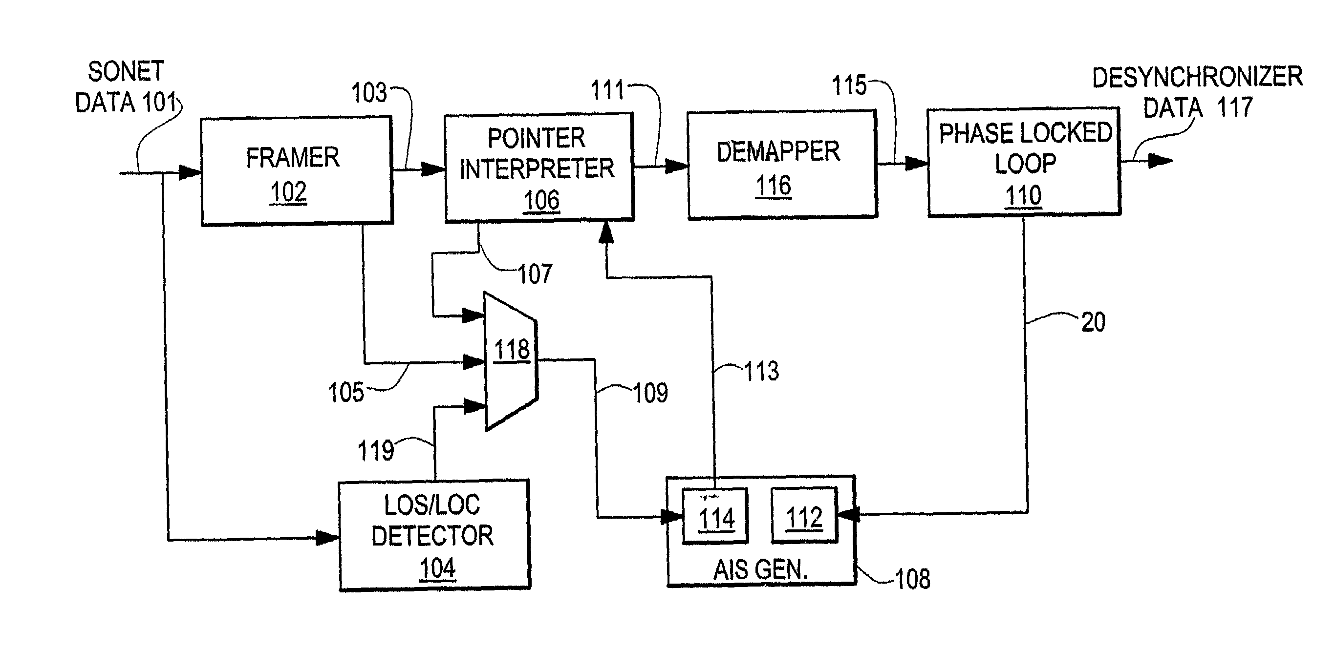
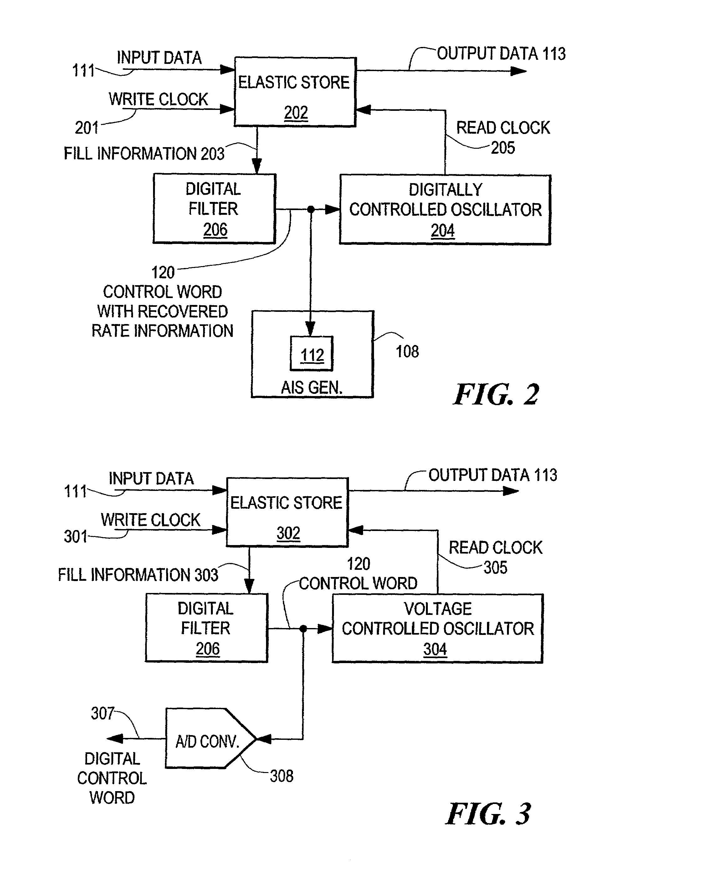
[0019]The protection device can include a framer, a pointer interpreter, a mapper, and a PLL and an error data generator and an error data rate generator. The error data generator, which operates as the oscillator for the protection device PLL, is coupled to the control word module such that, the error data rate generator receives the control word therefrom. The error data generator is responsive to the control word by providing a carrier signal having a data rate substantially equal to the recovered PLL data rate of the network device corresponding to the control word. The data generator is coupled to the first switching module and is responsive to the error signal by generating predetermined data that is indicative of a currently occurring error condition. The data generator, in conjunction with the error data rate generator, provides a plurality of predetermined error data at the recovered PLL data rate. The protection device receives the data stream from the switched data network connection and the protection device framer and pointer interpreter operate as in a normal network device, and the protection device PLL operates off the error data rate generator. The plurality of predetermined error data is provided to the protection device pointer interpreter to be inserted into the data stream at the appropriate locations. Because the protection device PLL is operated in conjunction with the error data rate generator the protection device will operate substantially at the PLL recovered data rate of the corresponding network device and thus data loss will be minimized since the protection device PLL does not have to acquire phase lock on the incoming signal.

Problems solved by technology

A PLL is most effective at filtering out high frequency jitter components, i.e., those with a frequency greater than 10 Hz., but is less effective at filtering out the low frequency wander components.
In addition, the large time constants required would result in a PLL that is slow to lock onto the reference signal and would cause long delays in recovering lock after a transient event.
During the transmission of a SONET / SDH message an error may occur resulting in a loss of data.
This loss of data may be caused by a loss of the data signal, a loss of the clock signal, a loss of frame, or another error condition may occur.
These errors may occur to one or more, or all, of the transported digital signals that have been multiplexed into the SONET / SDH message.
However, it is unlikely that the error condition data rate is equivalent to the payload data rate prior to the loss of signal condition occurring.
Accordingly, because the characteristic error data signal is at a different data rate than the payload data, the PLL may lose phase lock and have to reacquire phase lock before the output data will be valid.
Similarly, when the payload data is restored, the PLL may once again lose phase lock on the characteristic error data rate when the payload data is restored.
The time it takes the PLL to reacquire phase lock will result in erroneous data being sent, and a loss of data after restoration of the payload data.

Method used


Image

  • Method and apparatus for improving data integrity and desynchronizer recovery time after a loss of signal
  • Method and apparatus for improving data integrity and desynchronizer recovery time after a loss of signal
  • Method and apparatus for improving data integrity and desynchronizer recovery time after a loss of signal

Examples


Embodiment Construction

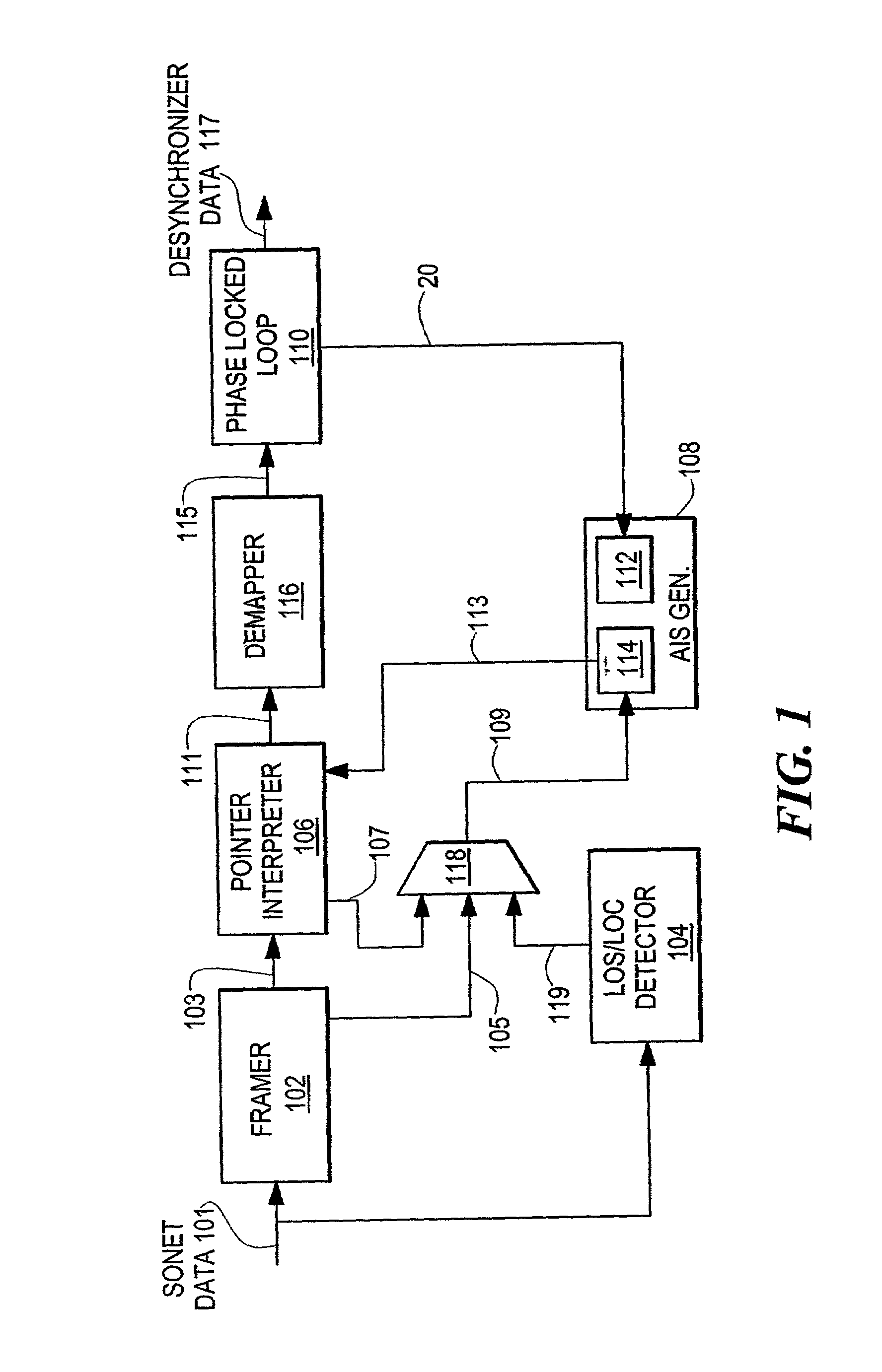
[0026]FIGS. 1–3 depict an embodiment of the present apparatus and a corresponding method for preventing data loss in network devices receiving a data stream of messages from a data network connection. The embodiments depicted herein monitors an incoming data stream to a network device or devices for an error condition that can include a loss of signal, loss of clock, a loss of frame error, or an existing AIS condition by detecting an error condition in the portions of the data messages that are used to provide indicia of an error condition. In the event an error condition is detected or an alarm indication signal (AIS) is received predetermined error data is generated and inserted into the data stream. The predetermined error data is provided at the same data rate as the valid output data provided by the network device. In this way, the network device will not have to adjust to a different data rate.

[0027]In particular, as shown in FIG. 1, the present apparatus and corresponding met...


PUM


Abstract

An apparatus and corresponding method for preventing data loss in network devices is disclosed. The present invention monitors an incoming data stream to a network device, or devices, and in the event that an error condition is detected, predetermined error data is inserted into the data stream, wherein the predetermined error data is provided at the same data rate as the recovered data rate internal to the network device. Thus, the network device will not have to adjust to a different data rate and potentially lose data during the adjustment period.

Description

CROSS REFERENCE TO RELATED APPLICATIONS[0001]N / ASTATEMENT REGARDING FEDERALLY SPONSORED RESEARCH OR DEVELOPMENT[0002]N / ABACKGROUND OF THE INVENTION[0003]In a synchronous communications network, digital payload data is carried on a particular clock frequency within a synchronous message format. This payload data may include both asynchronous digital data and synchronous digital data originating at a different data rate in a foreign digital network. The Synchronous Optical Network (SONET) and its European counterpart the Synchronous Digital Hierarchy (SDH) provide a standard format of transporting digital signals having various data rates, such as a DS-0, DS-1, DS-1C, DS-2, or a DS-3 signal and their European counterparts within a Synchronous Payload Envelope (SPE), or a container that is a part of a SONET / SDH STS-N / STM-N message frame. In addition to the digital data that is mapped and framed within the SPE or container, the STS-N / STM-N message frame also includes overhead data that ...

Claims


Application Information

Patent Timeline
Patent Type & Authority Patents(United States)
IPC IPC(8): H04L12/28H03L7/06H04J3/07H04L25/64H04Q11/04
CPCH04J3/076Y10S370/907H04J2203/006
Inventor SUBRAHMANYAN, RAVICANDAGE, ANTHONY B.
Owner MACOM CONNECTIVITY SOLUTIONS LLC
Learn More