
Multi-frequency transmitter using predistortion and a method of transmitting

a multi-frequency transmitter and predistortion technology, applied in the field of transmitters and transmitting methods, can solve problems such as non-linear distortion, system capacity reduction, and amplifier modification to reduce non-linear distortion, and achieve the effect of solving or reducing the problem of non-linear amplifiers

Inactive Publication Date: 2006-02-14
NOKIA NETWORKS OY
View PDF14 Cites 43 Cited by
  • Summary
  • Abstract
  • Description
  • Claims
  • Application Information

AI Technical Summary

Benefits of technology

[0013]It is an aim of embodiments of the present invention to provide a transmitter which can have only a single transmit path and which solves or at least mitigates the problems caused by a non linear amplifier.
[0017]Preferably the predistortion means are arranged to individually predistort each of the different signals before the plurality of different signals are combined by said combiner. This has the advantage that it is easy to ensure that different predistortion coefficients appropriate for the respective carrier frequency are applied to each of the signals which will be at the respective different carrier frequencies.
[0019]A feedback path may be arranged between the amplifying means and the predistorting means. Preferably, the predistorting means is arranged to compare the output from the amplifying means from the feedback path with the signals received by the receiving means and to provide, if necessary, at least one new predistortion value to be applied to at least one subsequent signal received by the receiving means. In this way, the predistorting means can adapt to changes in the operating conditions of the amplifier means.

Problems solved by technology

The leakage of power into adjacent channels is undesirable in that a reduction in system capacity and / or a reduction in signal quality results.
Linear amplifiers are known but even these amplifiers are not linear when operated near the peak capacity of the amplifier.
With predistortion, a signal is distorted prior to being input to the amplifier which causes the distortion.

Method used


Image

  • Multi-frequency transmitter using predistortion and a method of transmitting
  • Multi-frequency transmitter using predistortion and a method of transmitting
  • Multi-frequency transmitter using predistortion and a method of transmitting

Examples


first embodiment

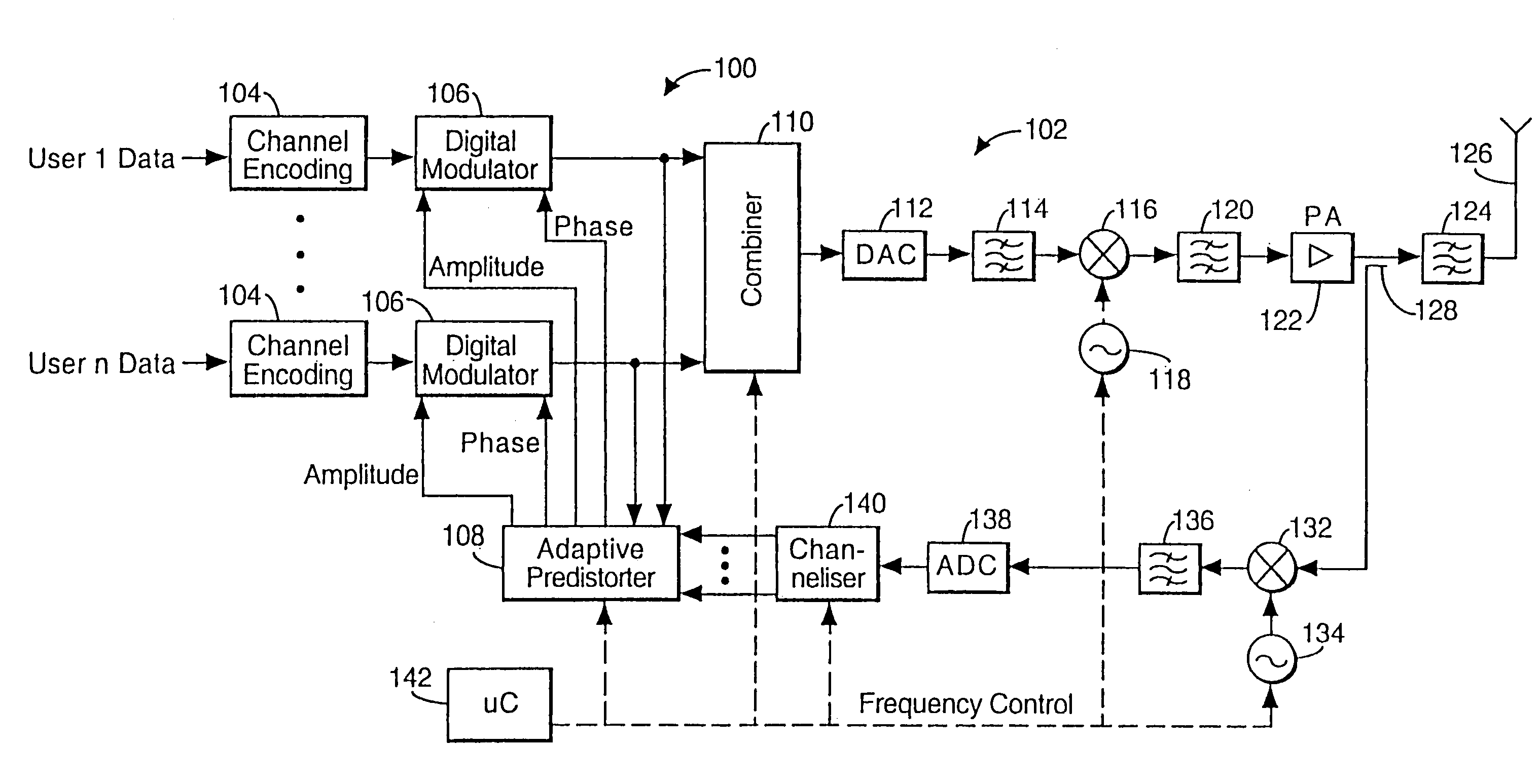
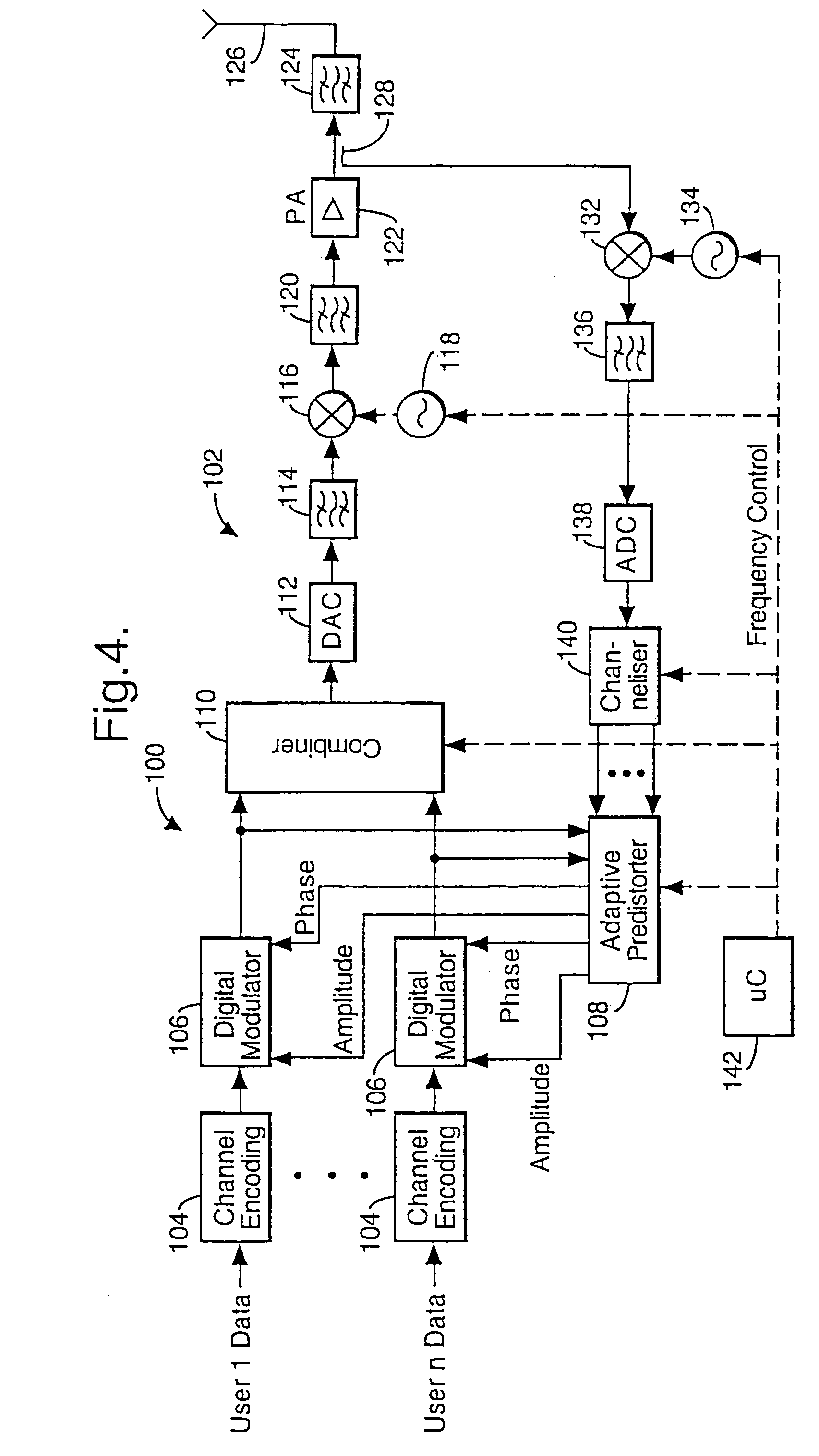
[0040]Reference will now be made to FIG. 4 which shows the present invention. In particular, the transmit part 102 of the base station 100 is shown. The base station 100 is in a cellular system of the type shown in FIG. 1.

[0041]The transmit part 102 of the base station 100 comprises N channel encoders 104 where N is the number of different frequencies on which the base station 100 will transmit signals. Each channel encoder 104 receives the data to be transmitted on the particular frequency associated with the given channel encoder 104. The data is placed in a suitable form for transmission. This may include digitising the data, encoding the data, interleaving the data and / or any other step required to be carried out. As mentioned hereinbefore, each channel is on a different frequency after the modulator. The signals output by the channel encoders 104 are in digital form and are at a baseband frequency. Coding, interleaving etc is performed on the digital baseband signals.

[0042]The ...

third embodiment

[0065]The frequency information provided by the microcontroller 142 is used by the predistorter 108 in the third embodiment to reconstruct the composite signal using any appropriate method. The methods require frequency information. One example is the inverse fast fourier transform technique which creates a spectral representation of the signal sampled in the time domain.

[0066]Reference will now be made to FIG. 6 which shows a third embodiment of the present invention. As with the second embodiment of the present invention, only the differences between the first and third embodiments will be discussed.

[0067]The channelizer 140 of FIG. 4 has been omitted from the embodiment of FIG. 6. The output of the analogue to digital converter 138 is thus connected directly to the input of the predistorter 108. As information is only available on the composite signal, the predistorter is arranged to create a reference.

[0068]Reference will now be made to FIG. 9 which shows a third embodiment of a...


PUM


Abstract

A multi frequency carrier transmitter comprises input means for receiving a plurality of different digital signals to be transmitted. The different signals are to be transmitted on different carrier frequencies. Amplifier means receive a composite signal comprising the different signals at the respective carrier frequencies and amplify the composite signal. Predistortion means predistort the plurality of digital signals prior to amplification of the composite signal by the amplification means. The predistortion provided by the predistortion means is subsequently altered in dependence on the difference between the input signals and the output at the amplifier means.

Description

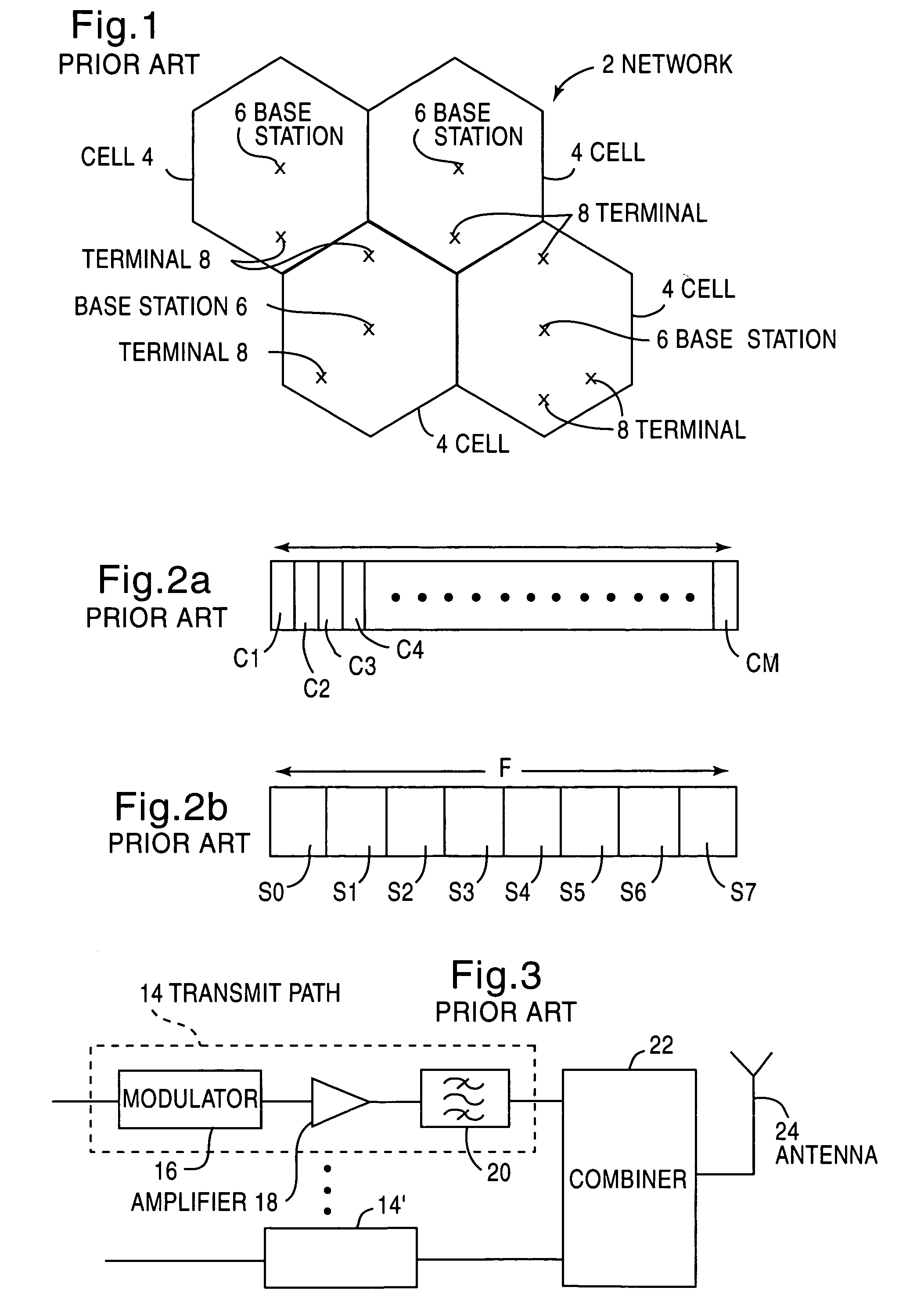
[0001]This application is a continuation of international application Ser. No. PCT / EP98 / 08445, filed Dec. 24, 1998.BACKGROUND OF THE INVENTION[0002]1. Field of the Invention[0003]The present invention relates to a transmitter and a method of transmitting and in particular, but not exclusively, for use in a telecommunications network.[0004]2. Description of the Related Art[0005]In known wireless telecommunication networks 2 such as illustrated in FIG. 1, the area covered by the network 2 is divided into a plurality of cells 4. Each cell 4 has associated therewith a base transceiver station 6. Each base station 6 is arranged to communicate with terminals located in the cell 8 associated with that base station 6. The terminals 8 may be mobile terminals which are arranged to move between the cells 4.[0006]Each base station 6 in the GSM (Global System for Mobile communications) is arranged to transmit N frequencies out of M available frequencies C1 . . . CM, as illustrated in FIG. 2a. Ea...

Claims


Application Information

Patent Timeline
IPC IPC(8): H04K1/02H04L25/03H04L25/49H04J1/02H03F1/32H04B1/04H04B1/62H04L27/36
CPCH03F1/3247H03F1/3282H04L27/368H04B1/62H03F2201/3206H04B1/04H03F2201/3233
Inventor POSTI, HARRI
Owner NOKIA NETWORKS OY
Learn More