Measurement of large strains in ropes using plastic optical fibers

a technology of optical fibers and strains, applied in the direction of distance measurement, instrumentation, force/torque/work measurement apparatus, etc., can solve the problems of reducing the strength of the rope, and causing damage to the rop

Inactive Publication Date: 2006-02-14
WILLIAMS JERRY GENE +2
View PDF4 Cites 24 Cited by
  • Summary
  • Abstract
  • Description
  • Claims
  • Application Information

AI Technical Summary

Benefits of technology

[0053]In accordance with the present invention, there is provided a method for the direct in situ measurement of large strains on the order of 0- to 15-percent or more in ropes using plastic optical fibers and Optical Time-Domain Reflectometer or other light time-of-flight measurement instrumentation such as Optical Frequency Domain Reflectometry. A plastic protective sheath and ingress-egress guides are incorporated to protect the plastic optical fiber in the marine environment and in the transition region of ingress into and egress out of the rope. A small braided rope optics carrier with minimal intrusion in the rope cross-section is one embodiment of the method which allows lateral compressive forces to be applied to the plastic optical fiber and restrain it from slipping and thus experience the same strain as the rope. The braided rope optics carrier can be incorporated in numerous rope configurations including braided, twisted, helical or wire rope constructions. A method is described for etching reflective interfaces at selected locations along the length of the plastic optical fiber. The method allows multiple reflective interfaces within a single fiber and thus provides the capability to measure strain along the entire length of the rope and within discrete length segments along the fiber's length. Multiplexing of the light signal allows monitoring of several plastic optical fibers and multiple segments within a fiber using a single light time-of-flight instrument. Interpretation of the data allows one to calculate the accumulated strain at any point in time and to determine if the rope has experienced local damage. Perfluorocarbon and polymethyl methacrylate are representative plastic optical fibers with the ability to track the cyclical large strains typically experienced by ropes used in the marine industry including mooring ropes used for station keeping on offshore platforms and marine ropes used to dock vessels.

Problems solved by technology

Ropes carry high tension loads and the service environment is often hostile, potentially causing damage to ropes.
Light-weight synthetic fiber mooring ropes including polyester ropes have high strength and adequate stiffness for mooring line applications, but are much more susceptible to damage than their steel counterpart.
The extreme conditions in the marine environment, especially under extreme loading conditions such as hurricanes, and due to possible damage caused by the intrusion of lines and cables from adjacent operations, can reduce the strength of the ropes.
Despite the use of current inspection procedures, however, there have been accidents, damages to property and equipment, injuries and deaths due to unexpected rope failures.

Method used


Image

  • Measurement of large strains in ropes using plastic optical fibers
  • Measurement of large strains in ropes using plastic optical fibers
  • Measurement of large strains in ropes using plastic optical fibers

Examples


Embodiment Construction

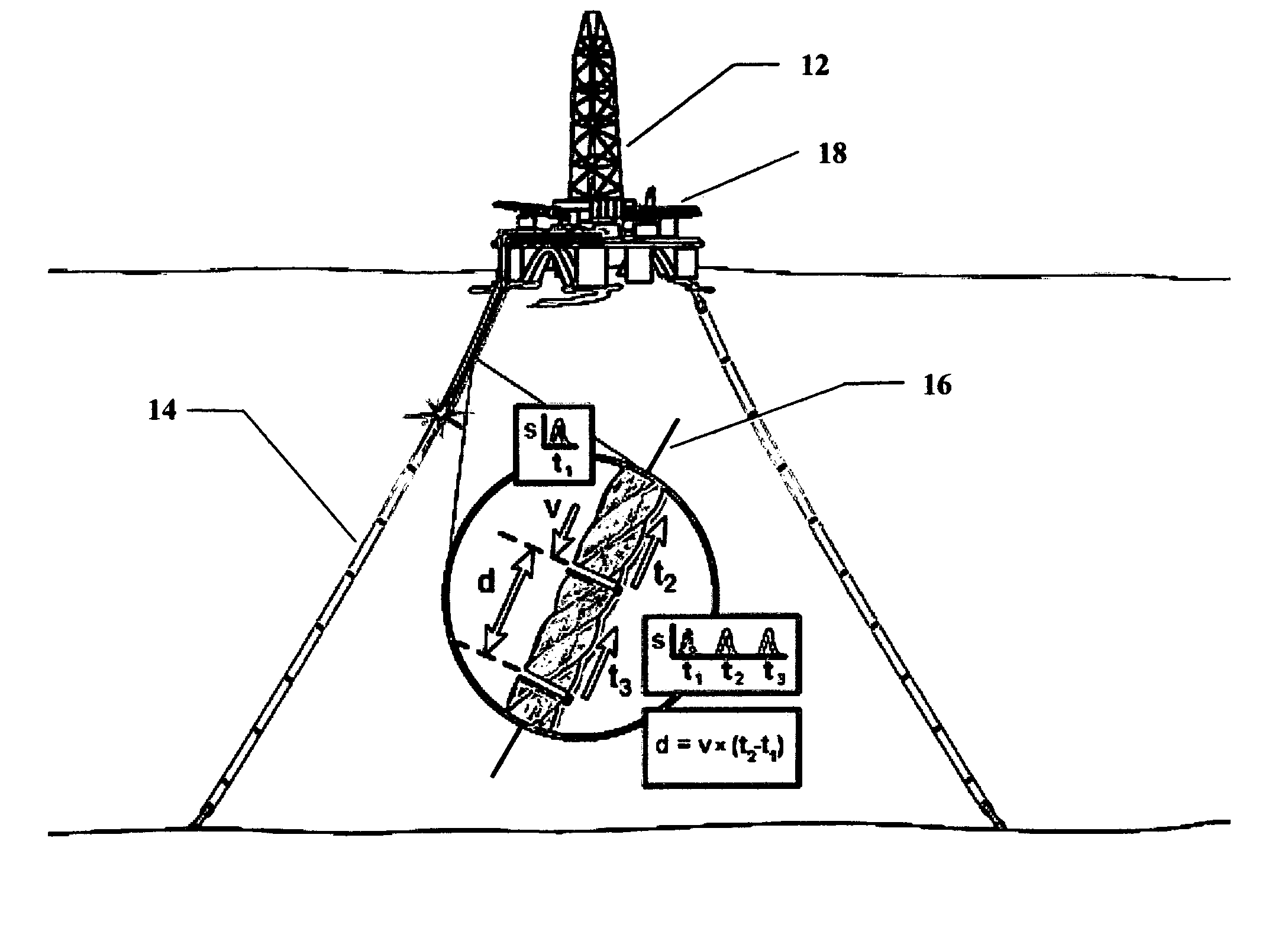
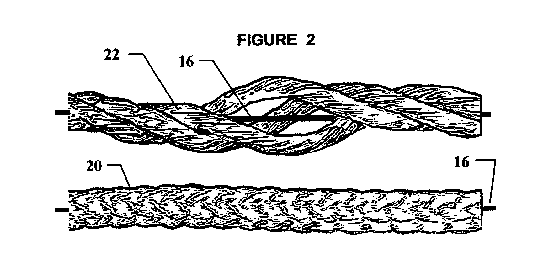
[0067]Generally speaking, the invention pertains to a method for making large in situ strain measurements, in particular, strain experienced in service by ropes such as offshore platform mooring ropes or docking ropes using a plastic optical fiber and a time-of-flight of light measurement technique involving instrumentation such as Optical Time Domain Reflectometry or Optical Frequency Domain Reflectometry. The application on an offshore platform mooring line features multiple sets of plastic optical fibers, multiple reflective surface within the plastic optical fiber to allow strain to be measured in discrete lengths of plastic optical fiber and thus the rope, and multiplexing to allow large numbers of measurements to be taken by a single Optical Time Domain Reflectometry or Optical Frequency Domain Reflectometry instrument.

[0068]Now referring to FIGS. 1 through 7, which teach the details of a method which can be exercised to achieve accurate reliable data for the measurement of la...


PUM

PropertyMeasurementUnit
radiusaaaaaaaaaa
lengthaaaaaaaaaa
braid angleaaaaaaaaaa

Abstract

A method for the direct measurement of large strains in ropes in situ using a plastic optical fiber, for example, perfluorocarbon or polymethyl methacrylate and Optical Time-Domain Reflectometer or other light time-of-flight measurement instrumentation. Protective sheaths and guides are incorporated to protect the plastic optical fiber. In one embodiment, a small rope is braided around the plastic optical fiber to impose lateral compressive forces to restrain the plastic optical fiber from slipping and thus experience the same strain as the rope. Methods are described for making reflective interfaces along the length of the plastic optical fiber and to provide the capability to measure strain within discrete segments of the rope. Interpretation of the data allows one to calculate the accumulated strain at any point in time and to determine if the rope has experienced local damage.

Description

[0001]This application claims priority from U.S. Provisional Patent Application No. 60 / 377,421, filed May 3, 2002 entitled “Optical Fiber Sensor for Measuring Strain in Synthetic Ropes”, and U.S. Provisional Application No. 60 / 443,311 filed Jan. 29, 2003 entitled “Method and Apparatus for Measuring Large Strains in Synthetic Fiber Ropes”; both herein incorporated by reference in their entirety.[0002]This invention was made with Government support under Contract No. DE-AC05-000R22725 awarded by the United States Department of Energy. The Government has certain rights in this invention.FIELD OF THE INVENTION[0003]The present invention relates to use of a plastic optical fiber and optical time-domain reflectometry or other instrumentation for the direct, in situ measurement of large strains imposed on ropes during service and, more particularly, in synthetic fiber ropes. The plastic optical fiber is integrated into the rope in several configurations which allow the plastic optical fibe...

Claims


Application Information

Patent Timeline
Patent Type & Authority Patents(United States)
IPC IPC(8): G02B6/12G01D5/353G01L5/10G02B6/10
CPCD04C1/02G01L5/105G01D5/35354G01D5/35316D07B1/145D07B2201/2096D07B2301/5577D07B2501/2061
Inventor WILLIAMS, JERRY GENESMITH, DAVID BARTONMUHS, JEFFREY DAVID
Owner WILLIAMS JERRY GENE
Why Eureka
Try Eureka