Method and system for automatic address allocation in a network and network protocol therefor

a network and address technology, applied in the field of telecommunications networks, can solve the problems of time-consuming and error-prone manual task of configuring each node with the associated address, installation and maintenance of additional hardware in the network and software, and the financial cost of additional hardware and software, so as to facilitate the use of network resources more efficiently

Active Publication Date: 2006-02-14
WSOU INVESTMENTS LLC +1
View PDF5 Cites 6 Cited by
  • Summary
  • Abstract
  • Description
  • Claims
  • Application Information

AI Technical Summary

Benefits of technology

[0034]The described method and system have the advantages of providing automatic allocation of addresses to the network devices, it does not require involvement of the operator for the allocation process, it also does not require the address server and / or additional hardware and software to support the process. Additionally, it generates device addresses that are arranged in a predetermined order, e.g. the addresses of the connected ports between two nodes may be sequential. It allows the use of the network resource more efficiently, e.g. to determine addresses of the connected devices by having limited information about the network, e.g. by knowing the address of one of the connected devices only, which otherwise would not be possible.

Problems solved by technology

The process of configuring each node with the associated addresses is a time-consuming and error-prone manual task.
However, this approach has a disadvantage of requiring installation and maintenance of additional hardware in the network and software on the server and on each network node, as well as the financial cost of the additional hardware and software.
It also provides allocation of device addresses in a random order which is not convenient and / or suitable in many situations.
The disadvantages of this method are that it requires a specialized hardware on the node and may require the address server in the network, and the addresses generated by one node are not related to those generated by another node, and in this sense are arbitrary, which is not suitable for many situations in the management of telecommunications networks.

Method used


Image

  • Method and system for automatic address allocation in a network and network protocol therefor
  • Method and system for automatic address allocation in a network and network protocol therefor
  • Method and system for automatic address allocation in a network and network protocol therefor

Examples


Embodiment Construction

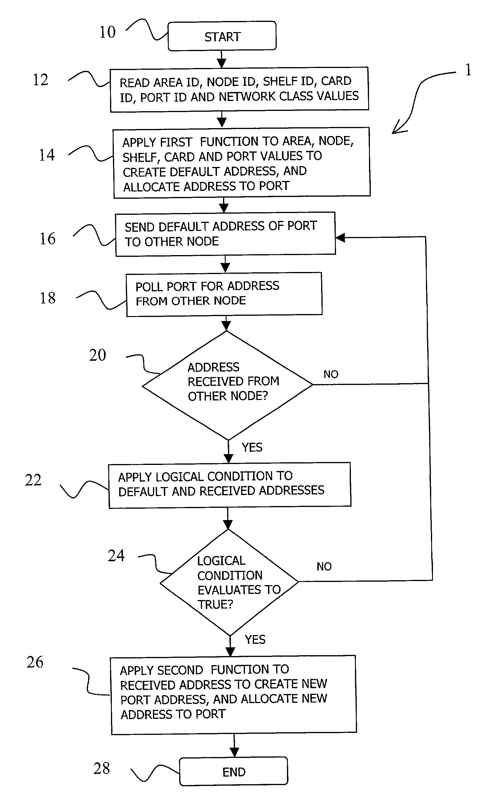
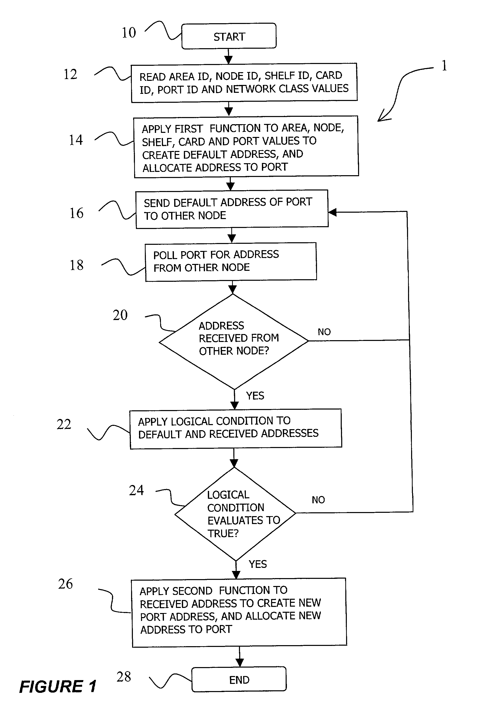
[0042]A method for automatic allocation of unique addresses to ports of the devices in a network according to a first embodiment of the invention is illustrated in FIG. 1 by flowchart 1. At the start of the method (box 10), a network administrator adds a new device to the network, e.g. a new node, powers up the node, provisions it with various cards, and configures the node with values for an area identifier, node identifier, and with an IP network type class value of “A”, “B” or “C”. The choice of the network class is performed before the network is created, and prior to the addition of any nodes to the network in function of the number of nodes that will be installed in the network. The definition of Class “A”, “B” and “C” networks is given in RFC 791, “INTERNET PROTOCOL, DARPA INTERNET PROGRAM, PROTOCOL SPECIFICATION”, published by the Internet Engineering Task Force (IETF), September 1981. A Class “A”, or / 8 network, is assigned to few networks in the Internet, where the network...


PUM


Abstract

A method and system for automatic allocation of port addresses in a network is provided. The node performs a self-discovery after initial power-up, and for each port on the node, using unique values associated with the port in the network hierarchy, applies a function that allows for an inverse function to the set of values to generate a default unique address for the port. A typical hierarchical structure in a network is the network area, node, and, within the node, the shelf, the card and the port. Next, the node sends a frame including the default port address and node identifier, from the port to a connected node. The node polls the port for a frame with network information associated with the connected port on the other node. If a frame is received from the other node, the node applies a logical condition to the default and received port addresses, and, if the condition is satisfied, applies another function to the received port address to generate a new unique address for the port, and maintains the new port address within the node. The method is described for IP networks but can be equally applied to ATM or Frame Relay networks, and for any nodes that support Sub-network Access Protocol (SNAP).

Description

[0001]This application claims the benefit of Provisional Application No. 60 / 318,315, filed Sep. 12, 2001.FIELD OF THE INVENTION[0002]The invention relates to telecommunications networks, and in particular, to a method and system for automatic allocation of addresses in a network and a network protocol therefor.BACKGROUND OF THE INVENTION[0003]Communication between devices in a network is achieved by communicating data along a path created by connecting a number of intermediate communication devices. The devices are usually grouped into networks of interconnected sub-networks, themselves comprising other sub-networks.[0004]The data exchange between two adjacent devices in the network is achieved by connecting a transmission media, such as copper wire or optical fiber, from a communication port on one device to a communication port on another device and sending the data between the devices in accordance with the addresses allocated to the ports of the devices on network nodes.[0005]On...

Claims


Application Information

Patent Timeline
IPC IPC(8): G06F15/16G06F15/00H04L29/12
CPCH04L61/2092H04L29/1232H04L61/5092
Inventor MARIAN, CONSTANTIN VIORELOPREA, DAN
Owner WSOU INVESTMENTS LLC
Why Eureka
Try Eureka