Flowchart programming for industrial controllers, in particular motion controllers

a technology for motion controllers and industrial controllers, applied in the direction of electric programme control, program control, instruments, etc., can solve the problems of restricting user's debugging options, limiting the library of icons available, and insufficient support of the existing flowchart editors for creating programs for both fields of applications, so as to increase the flexibility and ease of expression of users, and facilitate porting to different target systems. , the effect of increasing flexibility

Inactive Publication Date: 2006-02-14
SIEMENS AG
View PDF41 Cites 31 Cited by
  • Summary
  • Abstract
  • Description
  • Claims
  • Application Information

AI Technical Summary

Benefits of technology

[0038]Another advantage of the present invention is that adequate programming language commands, are made available for the user in the form of icons in the flowchart editor, for each underlying machine configuration or machine design. A user then has a programming environment which is adapted to the underlying hardware and is thus optimal in meeting existing requirements and boundary conditions. The library of icons of the flowchart editor is thus automatically adapted to the given hardware specifications (e.g., the underlying machine configuration).
[0039]In another advantageous embodiment of this invention, graphical elements containing the function interface of the corresponding subprograms can be generated automatically in flowchart notation from the corresponding user-defined subprograms of the textual language. This enables automatic generation of icons and the respective masks of systems from existing subprograms of the textual language or from additional subprograms optionally introduced into the textual language by the machine manufacturer and made available to the user in the flowchart editor. The function interface and transfer parameters of the subprograms of the textual language are generated automatically for flowchart icons. Due to this mechanism, original equipment manufacturers can transfer subprograms in textual language to the flowchart editor. An adapted and expanded library of icons is thus made available to the end user for flowchart programming.
[0040]In another advantageous embodiment of this invention, the automatically generated graphical elements may be used as language elements of the flowchart. This increases the library of flowchart elements available to the user, i.e., icons, due to the fact that these automatically generated icons can be used as normal language elements of the flowchart editor. It also increases the user's flexibility and ease of expression with regard to programming applications.
[0041]In another advantageous embodiment of this invention, the textual language is “structured text” according to the international standard IEC 6-1131 (International Electrotechnical Commission, 1992, Programmable controllers—Part 1: General information, IEC 6-11311, standard published by International Electrotechnical Commission). Due to the fact that IEC 6-1131 is a standardized language at the level of the textual language, it is readily possible to exchange it or combine it with other programming systems. In addition, when IEC 6-1131 is used as an intermediate language, it becomes easier to port to different target systems.
[0042]In another advantageous embodiment of the present invention, a user can transition between textual language, the contact plan and / or the function plan as forms of representation for expressing conditions as desired, since IEC 6-1131 is used as textual language on the structured text level. This provides increased flexibility for the user, and is an advantage in particular for formulating conditions, because the user can select the form of representation or description in which he or she is most experienced or which is most appropriate to the underlying problem. A user will generally use contact plans and / or function plans for representing binary links and structured text for formulating arithmetic calculations.
[0043]In another advantageous embodiment of the present invention, at least one loop and / or at least one parallel branch may be used as a language element in the flowchart view. In the flowchart editors conventionally used today, loops and frequently also branches are represented with the help of jump marks. However, due to the use of jumps and the respective targets marks, the program design may become complicated and difficult to reproduce (a “Go To problem”). Due to the fact that loops and parallel branches are available to the user as separate language elements, it becomes easier to develop and read the programs.

Problems solved by technology

Creation of programs for both fields of applications is not adequately supported by the existing flowchart editors.
Another disadvantage of the flowchart editors used today for programming industrial automation functions is that the diagrams created with these editors are either converted directly to executable processor code or to ASCII code, and must subsequently be interpreted in the respective target system through a run time-intensive process.
This system is not just inflexible with regard to porting and transfer of programs to other systems or machines, but does also restrict the user's debugging options.
Additional disadvantages of existing flowchart editors is that only a limited, rigid and inflexible library of icons is available, and that the processing sequence of icons and the corresponding function blocks is predetermined.
Further, existing flowchart editors frequently offer only a limited number of possibilities for formulating synchronization mechanisms, although such mechanisms are frequently required, in particular for programming applications in industrial automation.

Method used


Image

  • Flowchart programming for industrial controllers, in particular motion controllers
  • Flowchart programming for industrial controllers, in particular motion controllers
  • Flowchart programming for industrial controllers, in particular motion controllers

Examples


Embodiment Construction

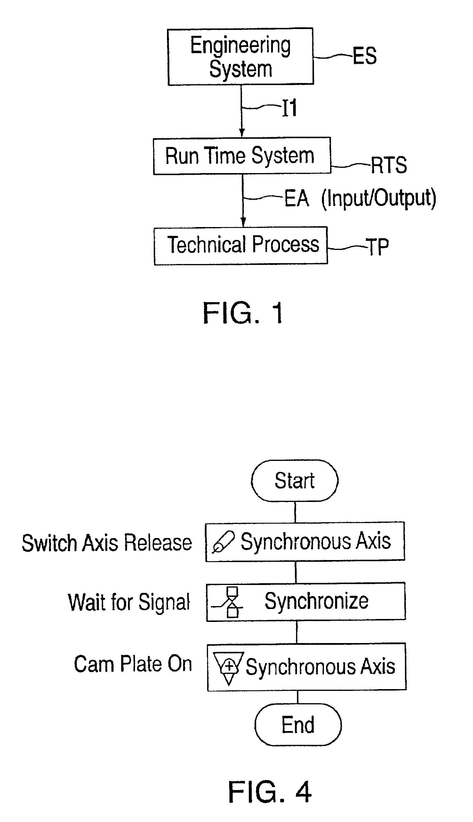
[0066]In FIG. 1, a block diagram shows that a technical process TP is controlled by the run time system RTS of an industrial controller. The connection between the run time system RTS and the controller, and the technical process TP, is bi-directional over the input / output EA. Programming of the controller and, thus, the specification of the behavior of the run time system RTS takes place in the engineering system ES. The engineering system ES contains tools for configuring, designing and programming machines, and for the control of technical processes. The programs generated in the engineering system are sent to the run time system RTS of the controller over information path I1. With regard to its hardware equipment, an engineering system ES usually comprises of a computer system with a graphical display screen (e.g., a video display unit), input means (e.g., a keyboard and mouse), a processor, working memory and secondary memory, a device for accommodating computer readable media ...


PUM


Abstract

A method and a device for graphical programming of industrial controllers, in particular motion controllers where a user is supported with regard to programmable controller functionality as well as with regard to motion functionality. A structured textual language is generated from graphical motion control flowcharts and converted in a processor-independent pseudo-code. Only the latter is loaded into the controller and converted to executable code.

Description

CROSS REFERENCE TO RELATED APPLICATIONS[0001]This application claims priority to the German applications No. 10038441.2, No. 10038440.4 and No. 10038439.0 all three filed on Aug. 7, 2000 and which are incorporated by reference herein in their entirety.FIELD OF THE INVENTION[0002]This invention relates to a method for programming industrial controllers, in particular motion controllers, where the user links graphical elements, in particular control structures and function blocks, with a graphical editor to form a flowchart that can be visualized on a display device.[0003]Furthermore, this invention relates to a device for programming industrial controllers, in particular motion controllers, where control structures and function blocks can be linked by a user with a graphical editor to form a flowchart that can be visualized on a display device.BACKGROUND[0004]In the industrial environment, it is known that graphical input aids and a display screen can be used for visualizing the cont...

Claims


Application Information

Patent Timeline
Patent Type & Authority Patents(United States)
IPC IPC(8): G09G5/00G05B19/05
CPCG05B19/056Y10S715/965
Inventor SCHMITT, REGINAWAGNER, PETER
Owner SIEMENS AG
Why Eureka
Try Eureka