Variable helix cutting tools

a cutting tool and variable technology, applied in the field of variable helix cutting tools, can solve the problems of not being suitable for a particular application, affecting the cutting effect of the tool, so as to improve the cutting action and tool life, reduce the manufacturing stress on the machine, and reduce the length of the chip

Inactive Publication Date: 2006-02-21
FLYNN CLIFFORD M +1
View PDF4 Cites 33 Cited by
  • Summary
  • Abstract
  • Description
  • Claims
  • Application Information

AI Technical Summary

Benefits of technology

[0010]The various alternative embodiments offer many significant advantages. Changing the helix generally removes the chip from the cutting field faster as chip flows up the changing helical flute. The changing helix also tends to break the chip into smaller chip length because the formation of the chip accrued at a helix that is different from the helix in the upper flute zone helix angle, which is out of the cutting zone. This change in shape or path is different than the formation shape of the chip, thus breaking the chip original shape.
[0011]The use of a variable helix also the contact angle of the cutting edge. This, in turn, retards chatter from developing because there is not a repeating contact of a straight line from flute to flute. In the continuing helix change of contact, the line of contact is always changing. The retarding of chatter improves cutting action and tool life, surface finish on the material, resulting in less manufacturing stress on the machines.
[0012]The invention further makes possible a faster feed rate or larger chip load per tooth because of chatter reduction in the cutting action. A deeper depth of cut is often possible due to chatter reduction in the cutting action. With high-helix tooling (i.e., 45 to 60 degrees), a corkscrew effect is a general handicap, pulling the cutter into the work piece or the cutter pulling the material upward. As such, high helix tools generally require corner protection for performance. With the variable helix made possible by this invention, corner protection is not needed, and the corkscrew effect is reduced or eliminated.

Problems solved by technology

While such variations have proven successful in various applications, they are also the source of certain disadvantages and limitations.
For example, such variations may weaken portions of the tool and may not be suitable for a particular applications (e.g., regarding milling time, rough cut, finish cut, etc.).
Furthermore, existing end-mills are not efficient for both rough cutting and finish cutting.

Method used


Image

  • Variable helix cutting tools
  • Variable helix cutting tools
  • Variable helix cutting tools

Examples


Embodiment Construction

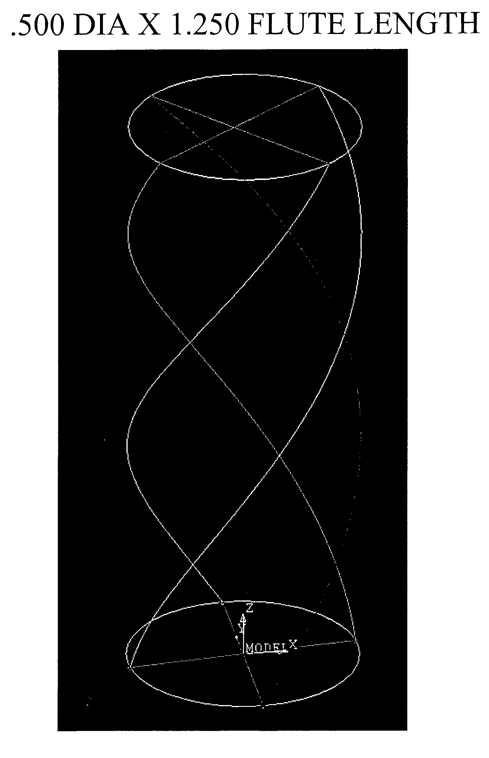
[0036]As discussed in the Background, this invention resides in tools, including but not limited to end mills, including a variable helix within a single flute, as well as variable helix(s) in multi-flutes. The various embodiments reduce or eliminate chatter, in aggressive cutting as well as in finish machining processes. This enables a deeper depth of cut or metal removal rate and, in many cases, an increase in tool life.

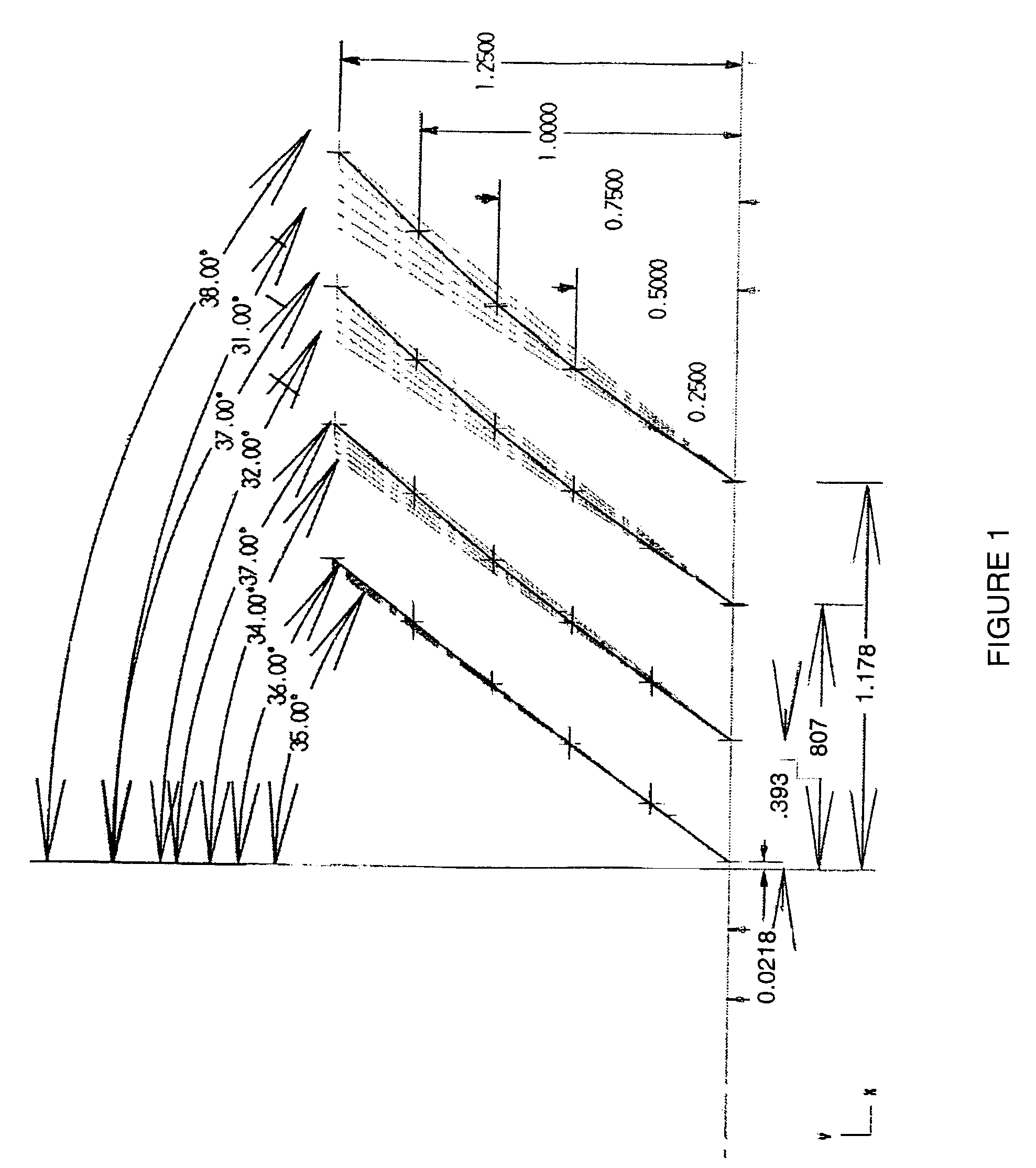
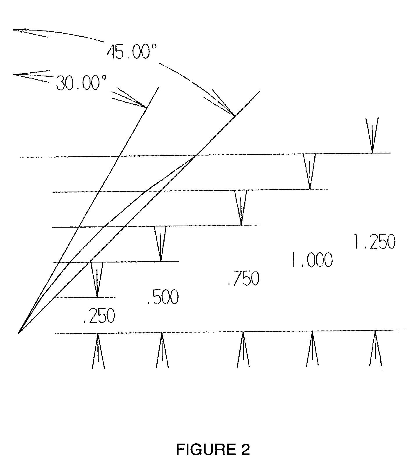
[0037]The design(s) are not limited to even number of flutes, or the total number in general in that the geometries may range a 1-flute tool to a multi-flute tool of 10 flutes or more. Additionally, the variable helix angle(s) according to the invention may change from flute to flute or may remain the same from flute to flute. The particular combination(s) is based on application and / or manufacturing procedure for a given product's needed results.

[0038]Generally speaking, the design is not limited to each flute not being the same variable helix or combination of a ...


PUM

PropertyMeasurementUnit
angleaaaaaaaaaa
angleaaaaaaaaaa
angleaaaaaaaaaa

Abstract

Tools, including end mills, include a flute having a helix which varies along the length of the tool. The invention is not limited in terms of the number of flutes, whether odd or even; helix change(s) within a flute or between flutes; or indexing between cutting edges or flutes. Nor is the invention limited in terms of materials used, and may employ carbide or high-speed steel grades of materials, ceramics, or any other material that will be used in the future for material removal in a rotary tool. According to the invention, a ‘slow’ or ‘high’ helix may be used at the end or starting point of the tool, depending upon the application. A slow helix at the end or starting point is desirable for a strong corner in ramping and plunging into the material. When a higher helix is used at the end transitioning to a smaller helix at the shank, the corner is also protected because of the helix change. The high helix at the tip may be needed for shearing action in a given material.

Description

REFERENCE TO RELATED APPLICATION[0001]This application claims priority from U.S. Provisional Patent Application Ser. No. 60 / 318,351, filed Sep. 10, 2001, the entire content of which is incorporated herein by reference.BACKGROUND OF THE INVENTION[0002]Rotary cutting tools such as end mills are used for various machining processes on workpieces. Such machining processes, generically referred to as milling operations, include the forming of slots, keyways, pockets, and the like. Several criteria must be considered with respect to the design of such tools, including the time for completing a machining operation, the amount of material removed in a cut, the quality of the cut, and the wear on the tool itself during the milling operation.[0003]To manufacture an end-mill tool, a grinder is typically used to grind a flute face and a corresponding cutting edge on the body of the tool. The grind (grinding operation) typically starts from a position adjacent an end of the body portion, continu...

Claims


Application Information

Patent Timeline
Patent Type & Authority Patents(United States)
IPC IPC(8): B23B51/00B23C5/10
CPCB23C5/10B23C2210/0485Y10T407/1948Y10T407/1966Y10T407/1952Y10T407/1946
Inventor FLYNN, CLIFFORD M.ST. LOUIS, PAUL
Owner FLYNN CLIFFORD M
Why Eureka
Try Eureka