Method of selectively annealing a needle

a selective annealing and needle technology, applied in the field of selective annealing needles, can solve the problems of selective annealing, inability to obtain with acceptable certainty curved needles, and inability to use curved needles, so as to facilitate selective hardening or softening of different portions, reduce waste, and increase efficiency

Inactive Publication Date: 2006-02-21
ETHICON INC
View PDF7 Cites 20 Cited by
  • Summary
  • Abstract
  • Description
  • Claims
  • Application Information

AI Technical Summary

Benefits of technology

[0011]While the method of this invention can be used for the manufacture of curved needles for any application, it is especially advantageous for the manufacturer of curved surgical needles. This improved method will facilitate the selective hardening or softening of different portions of the surgical needle, such as the point, body or attachment area. By controlling the relative hardness of one portion of the needle to another, complex needle geometries can be designed to take advantage of the varying degrees of stiffness at different portions of the needle. This will also lead to process improvements because of the increase in process control, leading to increased efficiencies and reduced waste.

Problems solved by technology

Unfortunately, the method described in the '412 patent requires the use of a wound coil and the placement of the straight felting needle within the center of the winding.
While this method is adequate for a straight needle, it is not practical for a curved needle because of the inability to position a curved needle within the center of the winding of the coil.
This is necessary due to the difficulty of controlling conventional processes, such as flame annealing or resistance annealing.
Selective annealing, as described in the '412 patent, while often desired, simply cannot be obtained with acceptable certainty for curved needles.
As a result, there currently exists an inability to selectively control the portion of the needle which is subjected to the annealing process.

Method used


Image

  • Method of selectively annealing a needle
  • Method of selectively annealing a needle
  • Method of selectively annealing a needle

Examples


Embodiment Construction

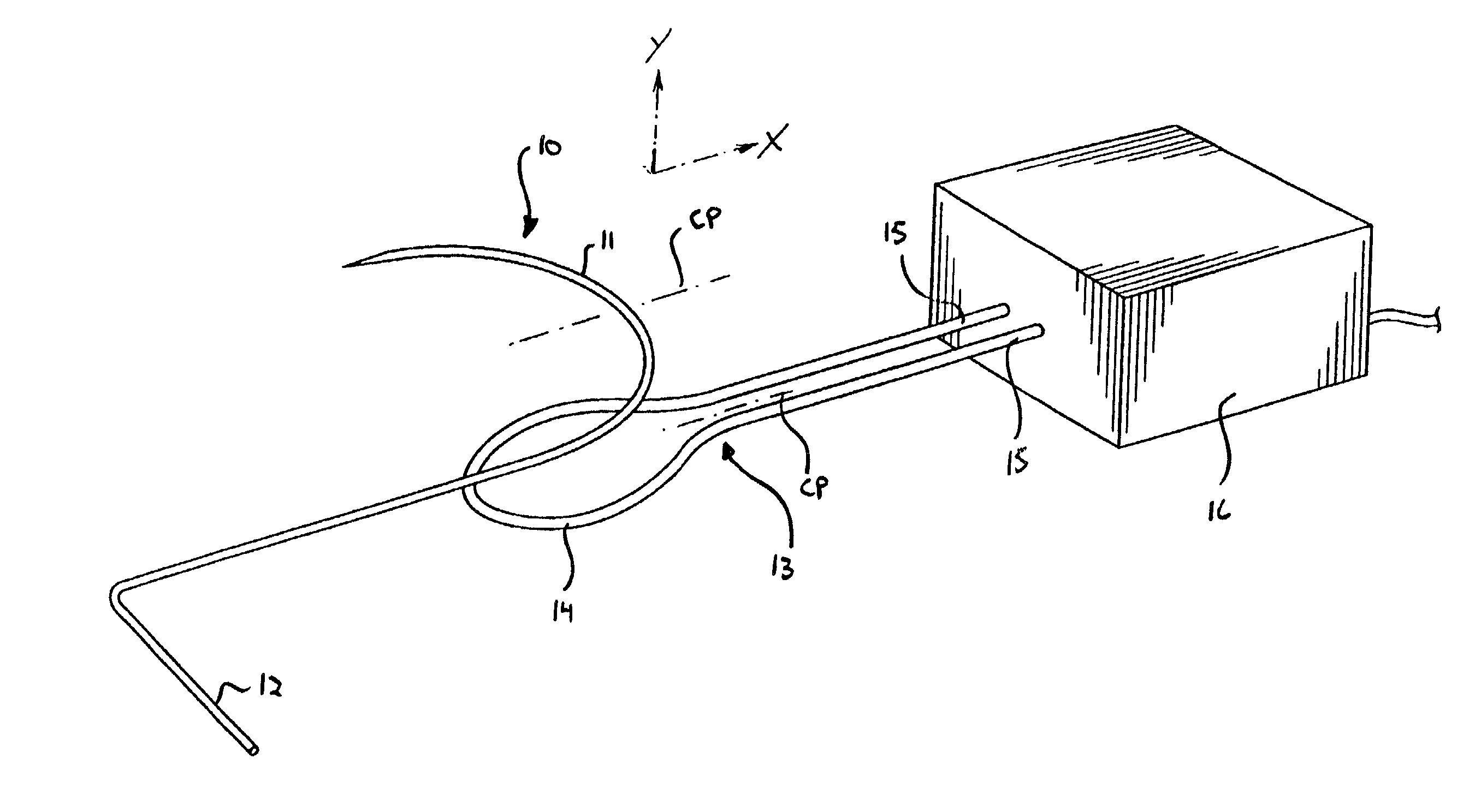
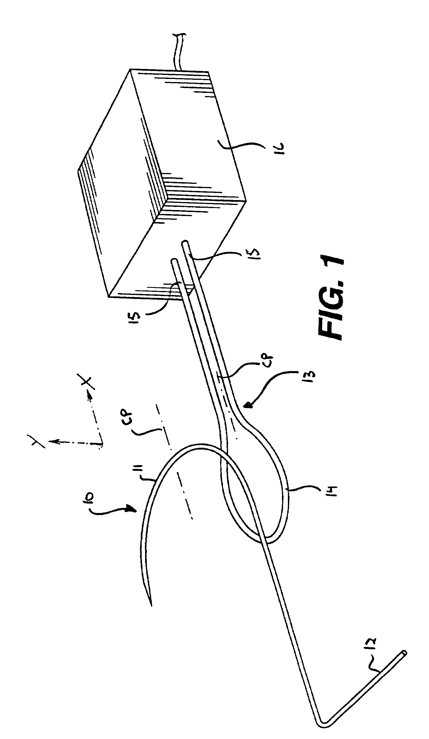
[0017]Referring initially to FIGS. 1–3, a needle 10 which has a curved body 11 is provided. Preferably, the needle has a diameter ranging between about 0.008 to about 0.061 inches. During the manufacturing of the curved needle from wire stock, the needle also includes a tail 12. A portion of the curved needle is positioned adjacent to an electromagnetic induction coil 13.

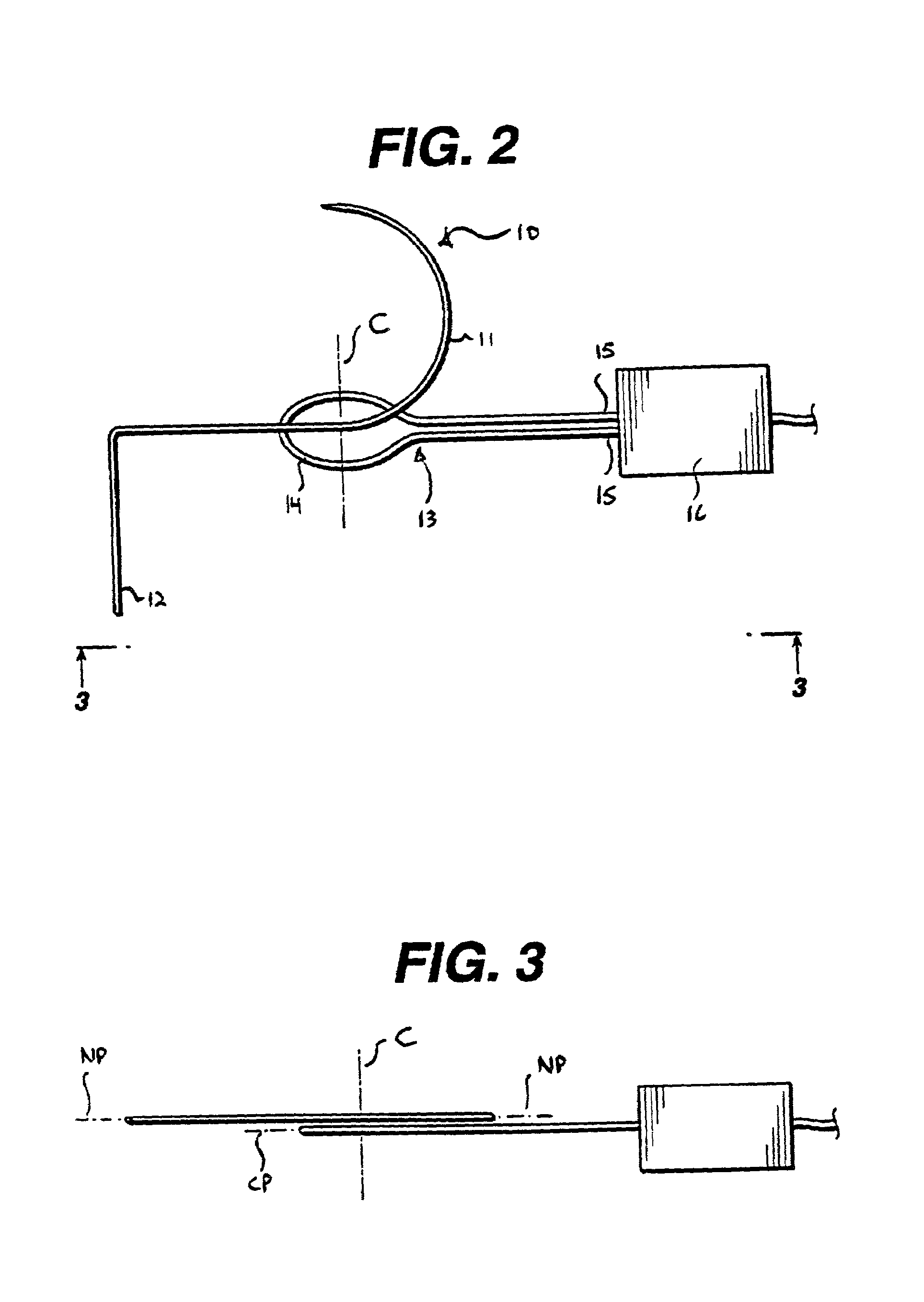
[0018]The induction coil has a flat configuration 14. The coil defines a coil plane designated as “CP” in FIG. 1, and parallel to the “X” axis also depicted in FIG. 1. The curved body 11 of the needle 10 lies in a plane designated as “NP” which is parallel to the coil plane CP of the flat induction coil 13. In this particular embodiment, the needle is positioned relative to the coil to provide the greatest application of heat to that portion of the needle which is subsequently attached to a suture following the selective annealing process. Specifically, this portion is ideally positioned at or near the center of the...


PUM

PropertyMeasurementUnit
diameteraaaaaaaaaa
lengthaaaaaaaaaa
lengthaaaaaaaaaa

Abstract

An improved method of selectively annealing a needle and the needle prepared by the improved method is disclosed. A curved needle is positioned adjacent a flat electromagnetic induction coil. The curved body of the needle is positioned in a plane parallel with the coil plane of the flat induction coil. A current is delivered through the coil to selectively heat and consequently selectively anneal a portion of the needle. The improved method enables the selective annealing of curved needles, and is especially useful for the manufacture of surgical needles.

Description

BACKGROUND OF THE INVENTION[0001]This invention relates to an improved method of selectively annealing a needle. More specifically, it relates to an improvement in the method of positioning a needle in close proximity with an electromagnetic induction coil and passing current through the coil to selectively anneal a portion of the needle.[0002]U.S. Pat. No. 3,753,412 describes a method of selectively hardening needles. A straight felting needle is positioned in a fixture which is connected to a high-frequency current. An electromagnetic coil is wound about the fixture. The turns of the coil have various diameters and spacings relative to each other. When current is applied to the coil, the needle is heated. The amount of heat applied to a specific section of the needle depends on the diameter and spacings of the coils at that section. Consequently, the needle is selectively hardened.[0003]Unfortunately, the method described in the '412 patent requires the use of a wound coil and the...

Claims


Application Information

Patent Timeline
Patent Type & Authority Patents(United States)
IPC IPC(8): C21D1/04A61B17/06B21G1/00C21D1/42C21D9/26
CPCA61B17/06066C21D9/26B21G1/00A61B2017/06028A61B2017/06071Y10S148/003C21D1/42C21D2221/00Y02P10/25
Inventor COLLIER, JOHNSTUNGURYS, LEON K.
Owner ETHICON INC
Why Eureka
Try Eureka