Antenna device for radio apparatus

a radio apparatus and antenna technology, applied in the direction of antenna details, antennas, basic electric elements, etc., can solve the problems of reduced gain, increased antenna loss, and body absorbs electric waves, so as to reduce the specific absorption rate and improve the gain during talk time

Inactive Publication Date: 2006-02-21
PANASONIC CORP
View PDF14 Cites 29 Cited by
  • Summary
  • Abstract
  • Description
  • Claims
  • Application Information

AI Technical Summary

Benefits of technology

[0006]It is therefore an object of the present invention to provide an antenna apparatus for wireless devices that improves gain during talk time and that decreases the specific absorption rate (SAR).

Problems solved by technology

When an antenna apparatus configured such as above is used, it occurs that the body absorbs electric waves and becomes an obstacle to the electric waves.
However, the following problem exists with conventional antenna apparatus.
That is, when an antenna element is unbalanced-fed, chassis current runs over ground plane 13 while communication is in progress, and radiation starts from ground plane 13 in a gripping position by the body (the hand, specifically) as a part of the antenna apparatus (unbalanced feeding scheme).
The electric waves are absorbed and obstructed by the body, which then results in the problem of reduced gain.
Moreover, with conventional antenna apparatus, when the specific absorption rate (SAR) goes over the level according to the guideline on specific absorption, antenna loss is increased and the transmission power of mobile telephone apparatus is decreased, which then results in the problem of narrowed communication area.

Method used


Image

  • Antenna device for radio apparatus
  • Antenna device for radio apparatus
  • Antenna device for radio apparatus

Examples


first embodiment

(First Embodiment)

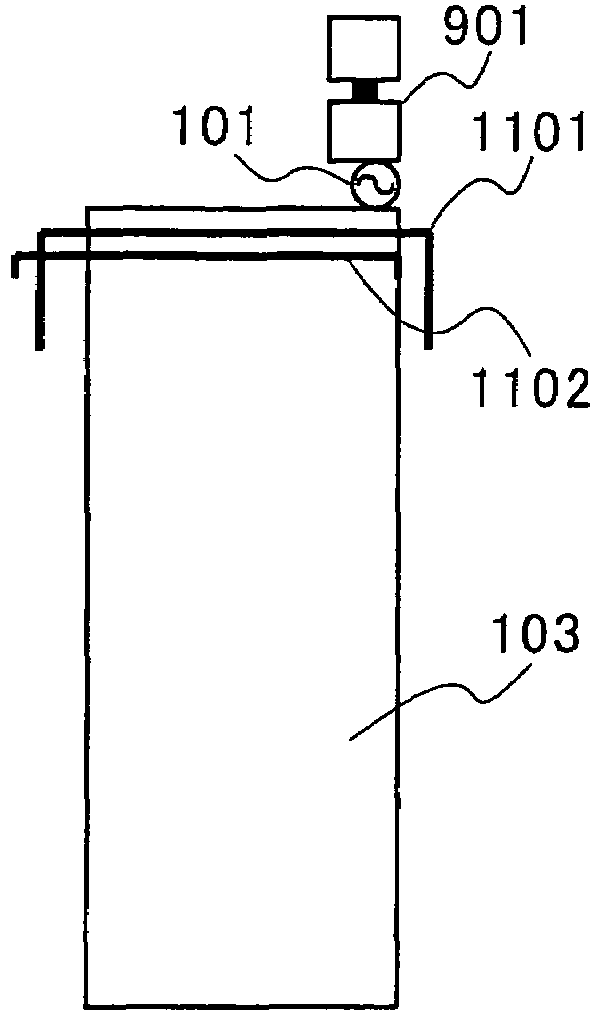
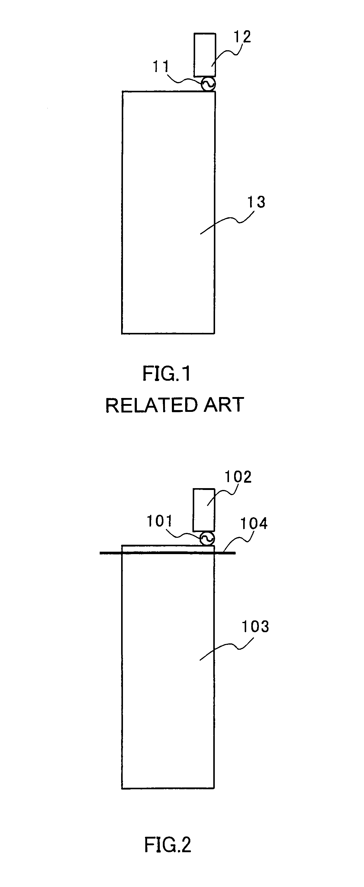
[0036]FIG. 2 is a configuration diagram of an antenna apparatus for wireless devices according to the first embodiment of the present invention. Referring to FIG. 2, feed point 101 performs unbalanced feeding to antenna element 102 through predetermined line patterns. Antenna element 102 has an arbitrary shape, which may be linear, helical, flat, and so on. Ground plane 103 is a ground layer configured on a circuit board and has electrically conductive characteristics. Parasitic element 104 is provided near antenna element 102 and ground plane 103, approximately parallel to the width direction of the ground plane. Also, parasitic element 104 is configured in a length to operate as a director when provided so as to be on the side of the human head (hereinafter simply “the body” unless indicated otherwise) with respect to ground plane 103 during talk time, and in a length to operate as a reflector when provided so as to be on the opposite side from the body with resp...

second embodiment

(Second Embodiment)

[0042]FIG. 4, FIG. 5, and FIG. 6 are each a configuration diagram of an antenna apparatus for wireless devices according to the second embodiment of the present invention. Parts identical to those in FIG. 2 are assigned the same numerals as in FIG. 2 without further explanation.

[0043]To use a parasitic element in the antenna apparatus, such a parasitic element is needed that has a predetermined length in accordance with the frequency that is used. Consequently, to make the size of the ground plane and the chassis smaller, work that shortens the length of the parasitic element is required.

[0044]Referring to FIG. 4, inductor 302 is installed in the middle of parasitic element 301, so that the element length can be shortened.

[0045]Referring to FIG. 5, parasitic element 401 is bent approximately at a right angle at predetermined distance from both ends so as to shorten the length of the width direction and make the configuration simpler than when inductor 302 is insta...

third embodiment

(Third Embodiment)

[0049]A case will be described here with the present embodiment where the shapes of the parasitic elements used in the first embodiment and the second embodiment are changed.

[0050]FIG. 7A to FIG. 7D are each a configuration diagram of a parasitic element according to the third embodiment of the present invention. FIG. 7A shows parasitic element 104 of a linear shape in FIG. 2 changed to parasitic element 601 of a band shape. While changes in the impedance characteristics of linear parasitic element 104 tend to be sharp and make impedance matching difficult, with band-shaped parasitic element 601, changes in the impedance characteristics can be moderated. As a result, it is possible to reduce antenna loss. Moreover, by employing the band shape, the antenna can be configured in a more simple way such as sticking it on a back plane of chassis.

[0051]Similarly, FIG. 7B to FIG. 7D show the linear parasitic elements of FIG. 4 to FIG. 6 changed to band-shaped parasitic ele...


PUM


Abstract

Feed point (101) performs unbalanced feeding to an antenna element (102). A parasitic element (104) is provided near the antenna element (102) and a ground plane (103), approximately parallel to the width direction of the ground plane (103). Moreover, the parasitic element (104) is configured in a length to operate as a director when provided on the side of the body with respect to the ground plane (103) during talk time and in a length to operate as a reflector when provided on the opposite side from the body with respect to the ground plane (103). By this means, it is possible to improve gain and reduce the specific absorption rate (SAR) during talk time.

Description

TECHNICAL FIELD[0001]The present invention relates to an antenna apparatus for wireless devices and is applicable to, for instance, portable mobile wireless devices.BACKGROUND ART[0002]FIG. 1 shows an example of antenna configuration for use for portable mobile wireless devices (referred to as portable mobile communication terminals or simply portable communication terminals) typified by portable telephone devices and mobile wireless devices.[0003]FIG. 1 is a configuration diagram of a conventional antenna apparatus. In this drawing, feed point 11 feeds antenna element 12. Antenna element 12 has an arbitrary shape, which may be linear, helical, and flat, and radiates electric waves when fed. Ground plane 13 is a circuit board or the like. The length of the length direction of ground plane 13 varies depending on the frequency band of the system that is used and the models of mobile telephone devices and is about ⅜ wave length in the 800 MHz band.[0004]When an antenna apparatus config...

Claims


Application Information

Patent Timeline
Patent Type & Authority Patents(United States)
IPC IPC(8): H01Q1/24H01Q19/26H01Q1/36H01Q1/38H01Q5/10H01Q19/32H04B7/26
CPCH01Q19/32H01Q1/245
Inventor EGAWA, KIYOSHIITO, HIDEO
Owner PANASONIC CORP
Why Eureka
Try Eureka