
Optical fiber strain sensor device and strain detection method

a technology of optical fiber and strain sensor, which is applied in the direction of optical radiation measurement, force measurement by measuring optical property variation, instruments, etc., can solve the problems of electromagnetic interference, waveform not necessarily uniform, and technique subject to electromagnetic interference

Inactive Publication Date: 2006-02-21
NAT INST OF ADVANCED IND SCI & TECH
View PDF6 Cites 10 Cited by
  • Summary
  • Abstract
  • Description
  • Claims
  • Application Information

AI Technical Summary

Benefits of technology

[0011](3) The optical fiber strain sensor device is free from the effect of electromagnetic interference because the FBG sensor converts measurement parameters into an optical signal.
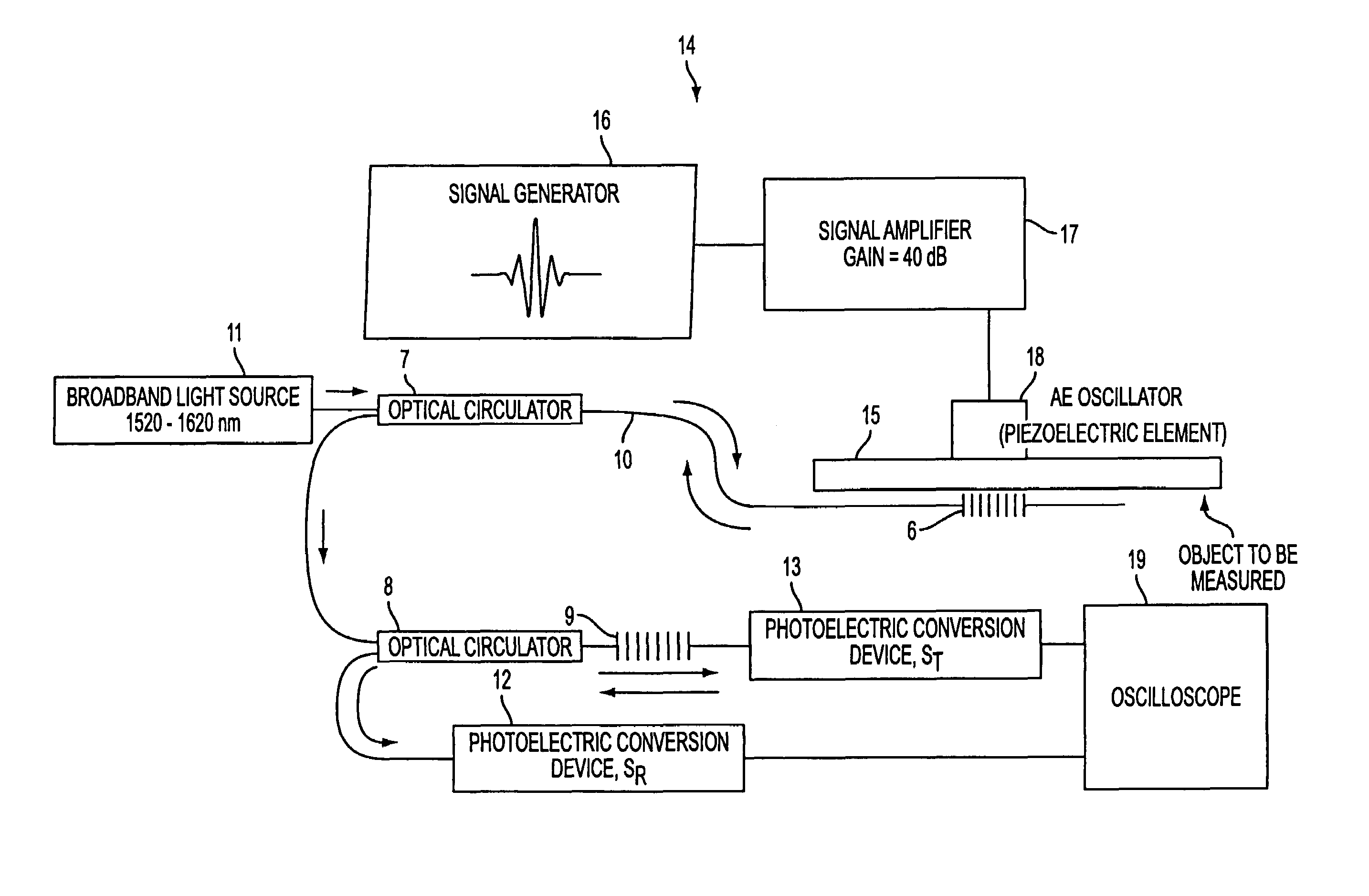
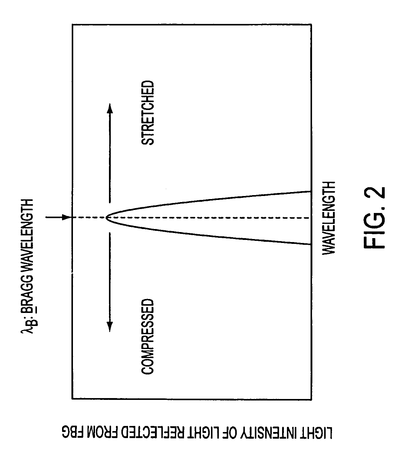
[0015]A strain detection method of the present invention provides an optical fiber strain sensor device, wherein an FBG sensor including an optical fiber with an FBG written therein is mounted onto an object to be measured, a broadband wavelength light ray is incident on the FBG sensor, a light ray reflected from the FBG sensor is incident on a filter, and by using the filter, the optical fiber strain sensor device processes the light ray reflected from the FBG sensor taking advantage of the fact that the center wavelength of the light ray reflected from the FBG sensor varies in proportion to a strain sensed by the FBG sensor and thereby detects a change in the strain of the FBG sensor.

Problems solved by technology

Since the known piezoelectric technique used to detect AE directly converts measurement parameters into an electrical signal, that technique is subject to the effect of electromagnetic interference.
On the other hand, in the proposed optical technique, the FBG sensor converts measurement parameters into an optical signal, and is thus free from the effects of electromagnetic interference, however, the detected waveform does not necessarily reflect the original shape of the AE, and may sometimes suffer from distortion.
For this reason, the technique is unable to track and detect a dynamic strain change.

Method used


Image

  • Optical fiber strain sensor device and strain detection method
  • Optical fiber strain sensor device and strain detection method
  • Optical fiber strain sensor device and strain detection method

Examples


Embodiment Construction

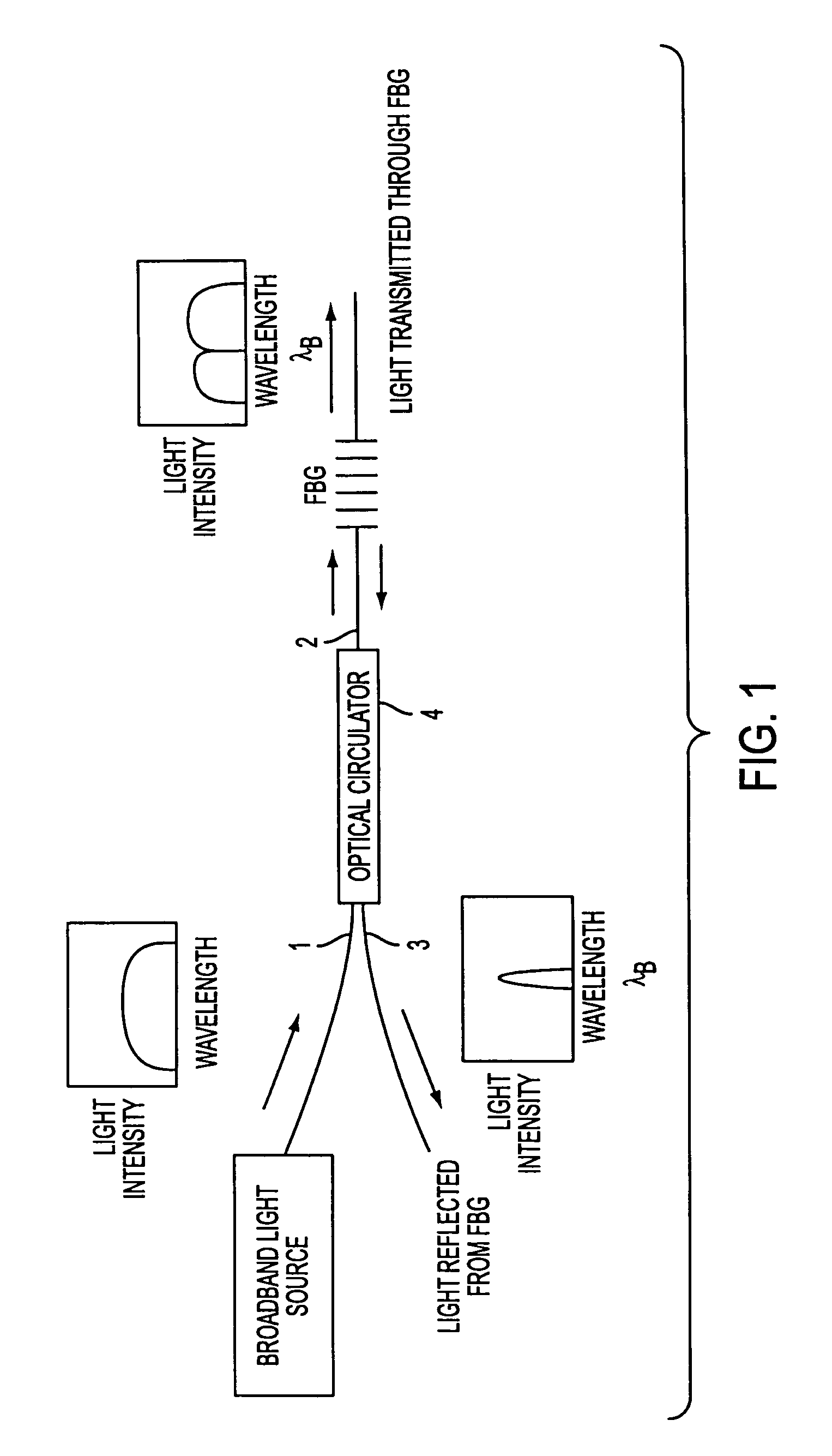
[0028]The operating principle of the FBG is discussed with reference to FIG. 1. The FBG is structured such that the optical fiber core is periodically varied in refractive index, and reflects only an optical signal in a narrow band having twice the product of the refractive index and the period of changes of the refractive index as a center wavelength (referred to as the “Bragg wavelength”).

[0029]As shown in FIG. 1, when a broadband light ray is incident on the FBG a light ray transmitted through the FBG has an intensity distribution lacking the Bragg wavelength region. A light ray reflected from the FBG has an intensity distribution having a narrow band centered on the Bragg wavelength. As shown in FIG. 1, optical circulator 4 is an optical element that transfers a light ray from a terminal 1 to a terminal 2 only, and from the terminal 2 to a terminal 3 only.

[0030]When the FBG suffers from strain and a temperature change, the Bragg wavelength thereof changes. More specifically, giv...


PUM


Abstract

To provide an optical fiber strain sensor device and a strain detection method, for measuring precisely AE and for detecting effectively a rapid strain change due to a shock load, an optical fiber strain sensor device includes an FBG sensor mounted on an object to be measured, a broadband light source for directing a broadband wavelength light ray to the FBG sensor, and an FBG filter that reflects or transmits a light ray reflected from the FBG sensor, and, using the FBG filter, the optical fiber strain sensor device processes and detects a change in the center wavelength of the light ray that has been incident from the broadband light source and then has been reflected from the FBG sensor.

Description

BACKGROUND OF THE INVENTION[0001]1. Technical Field of the Invention[0002]The present invention relates to a method for detecting a strain change using a fiber Bragg grating (hereinafter referred to as “FBG”) sensor and, more specifically, relates to a method for detecting an acoustic emission (hereinafter referred to as “AE”) that is caused by infinitesimal damage in a material or a structural body.[0003]The present invention is used when the soundness of a structural body is assessed by the AE method by generating an acoustic wave with a piezoelectric element, or when a fast strain change due to a shock load is detected. The present invention can be used in the structural examination of the soundness of mechanical constructions such as automobiles, aircraft, bridges, buildings, etc.[0004]2. Description of the Related Art[0005]Piezoelectric elements have been conventionally used to detect AE, and a strain gauge has been used to detect a shock load.[0006]A technique has been propose...

Claims


Application Information

Patent Timeline
IPC IPC(8): G01N21/00G01B11/16G01D5/353G01L1/24G01M11/08
CPCG01B11/165G01D5/35316G01M11/083G01L1/246G01D5/35354G01B11/18
Inventor TSUDA, HIROSHI
Owner NAT INST OF ADVANCED IND SCI & TECH
Learn More