Lens driving apparatus

a driving apparatus and lens technology, applied in the field of lens driving apparatus, can solve the problems of difficult or impossible to reserve space for new parts, counter to the standardization and part saving configuration, and the actuator unit cannot accurately follow the tracking error signal, etc., to achieve the effect of less or no additional new parts and simple structur

Inactive Publication Date: 2006-02-21
PIONEER CORP
View PDF8 Cites 23 Cited by
  • Summary
  • Abstract
  • Description
  • Claims
  • Application Information

AI Technical Summary

Benefits of technology

[0010]The present invention is proposed in view of the above mentioned problems. It is therefore an object of the present invention to provide a lens driving apparatus in which a rotationally driving force of a moving unit can be suppressed while employing a rather simple structure with less or no additional new part.

Problems solved by technology

If the rotationally driving force is induced, the actuator unit cannot make the moving unit accurately follow the tracking error signal or the focus error signal.
However, by this method, it is difficult or impossible to reserve the space to newly add a part for canceling the rotationally driving force, and this runs counter to the standardization and the part saving configuration.

Method used


Image

  • Lens driving apparatus
  • Lens driving apparatus
  • Lens driving apparatus

Examples


Embodiment Construction

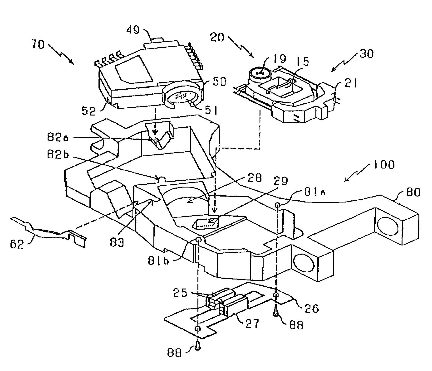
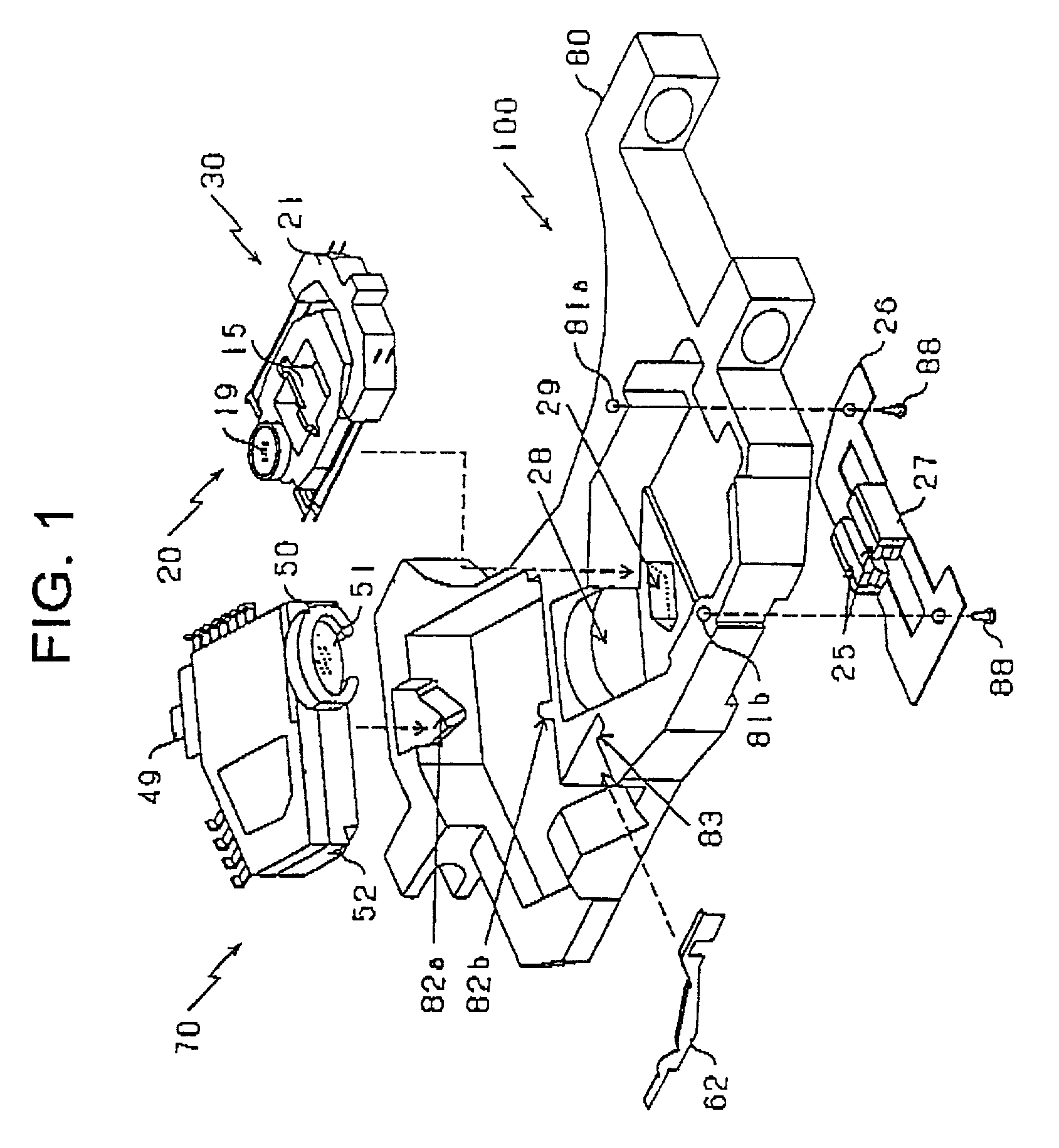
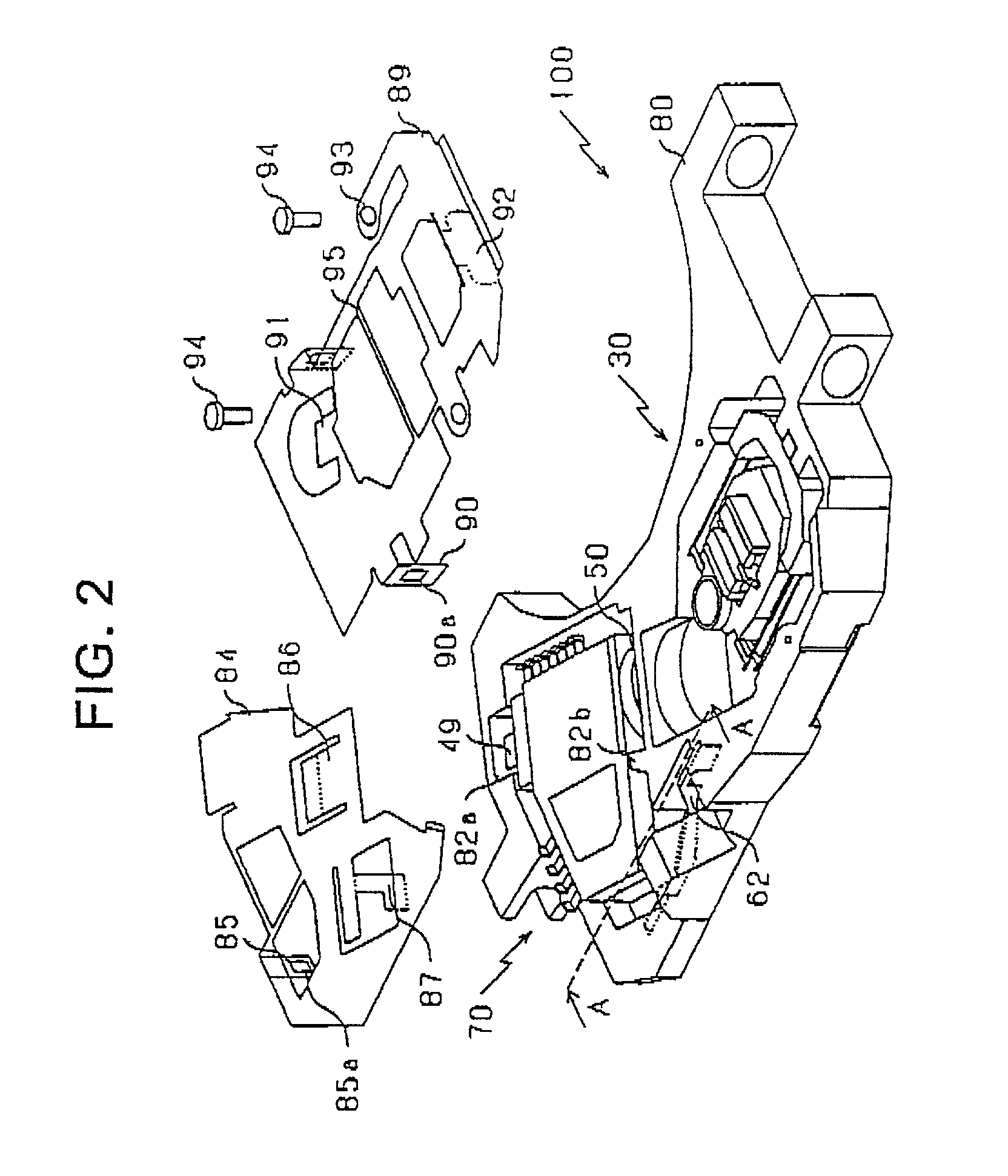
[0047]A lens driving apparatus 100 according to an embodiment of the present invention will be explained below with reference to the drawings. The lens driving apparatus 100 according to this embodiment is provided with: a module 70 serving as one example of an optical part accommodating module for an optical pickup in which optical parts, such as two light emitting devices for emitting light beams whose wave length are different from each other, a grating, a beam splitter, a light receiving device and the like are integrated into a single resin package unit; and an actuator unit 30 in which an objective lens is built. So, the lens driving apparatus 100 is miniaturized and thinned. Also, such a lens driving apparatus 100 is designed so as to carry out a grating adjustment, which is typically done, from an outer side of the module 70. The entire configuration of the lens driving apparatus 100 will be described below with reference to FIG. 1 and FIG. 2. By the way, FIG. 1 and FIG. 2 a...


PUM

PropertyMeasurementUnit
wave lengthaaaaaaaaaa
angleaaaaaaaaaa

Abstract

A lens driving apparatus for driving a movable body in a focus direction and a tracking direction is provided with: a holder, to which a focus coil, a tracking coil and a lens are installed, to thereby constitute the movable body; and a magnetic circuit for applying magnetic fluxes to the focus coil and the tracking coil, to thereby drive the movable body in the focus direction and the tracking direction. The tracking coil includes two sets each having upper and lower two coils arrayed in the focus direction such that the two sets are arrayed in the tracking direction. The magnetic circuit applies the magnetic fluxes opposite to each other along a jitter direction, with respect to the upper two coils and the lower two coils without applying the magnetic fluxes with respect to portions adjacent to the upper and lower two coils.

Description

BACKGROUND OF THE INVENTION[0001]1. Field of the Invention[0002]The present invention relates to a lens driving apparatus for a disc player for recording onto and / or reproducing from a disc, which is a record medium for a CD (Compact Disc), a DVD or the like.[0003]2. Description of the Related Art[0004]There is a lens driving apparatus for a disc player for recording onto and / or reproducing from a disc as a record medium for the CD or the DVD to correspond to a demand for a smaller, lighter and thinner structure The lens driving apparatus can be roughly classified into: a semiconductor optical unit having a light emitting element for emitting a light beam, a grating, a beam splitter, a light receiving device and the like; and an actuator unit having a moving portion. The semiconductor optical unit can be drastically miniaturized by wiring the semiconductor elements such as the light emitting element, the light receiving element and the like in a chip state, and then packaging them t...

Claims


Application Information

Patent Timeline
Patent Type & Authority Patents(United States)
IPC IPC(8): G11B7/00G11B7/08G11B7/09G11B7/125G11B7/135G11B7/22
CPCG11B7/0933G11B7/0935G11B7/1359G11B7/1395G11B7/1275G11B7/082G11B7/0903G11B2007/0006G11B7/22
Inventor GOAMI, KAZUTAKASUZUKI, JUNTAKAYA, SHIGERUSASANUMA, SHIGEYUKIFUJINOKI, SHINICHI
Owner PIONEER CORP
Why Eureka
Try Eureka