
SIL near-field flying head structure to control gap between disc and SIL with three sensor points in front of lens holder

a near-field flying head and lens holder technology, applied in the field of optical recording technology, can solve the problems of low product yield rate and high fabrication difficulty, and achieve the effects of preventing contact with the sil, high parallelism, and stable and accurate exposure operation

Inactive Publication Date: 2006-02-21
IND TECH RES INST
View PDF1 Cites 12 Cited by
  • Summary
  • Abstract
  • Description
  • Claims
  • Application Information

AI Technical Summary

Benefits of technology

[0007]The present invention has been accomplished to provide a SIL (solid immersion lens) near-field flying head flying state control structure, which eliminates the aforesaid drawbacks. It is the main object of the present invention to provide a SIL near-field flying head flying state control structure, which detects and correct the posture of the SIL, so as to keep the SIL and the optical disk in a high parallelism, achieving a stable and accurate exposure operation and preventing contact of the SIL with the optical disk.
[0008]It is another object of the present invention to provide a SIL near-field flying head flying state control structure, which is easy to fabricate.

Problems solved by technology

This precision requirement results in high fabrication difficulty and low product yield rate.

Method used


Image

  • SIL near-field flying head structure to control gap between disc and SIL with three sensor points in front of lens holder
  • SIL near-field flying head structure to control gap between disc and SIL with three sensor points in front of lens holder

Examples


Embodiment Construction

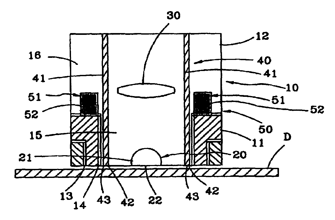
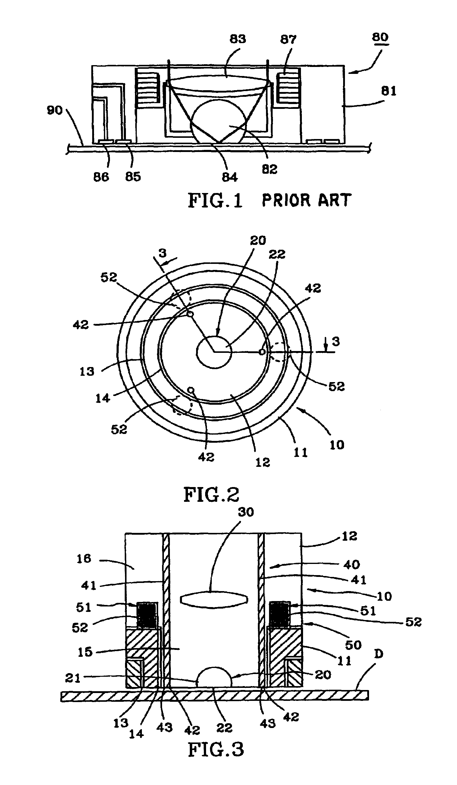
[0013]Referring to FIGS. 2 and 3, a SIL (solid immersion lens) near-field flying head flying state control structure in accordance with the present invention is shown comprising a slider 10, a SIL (solid immersion lens) 20, a focusing lens 30, a distance detection unit 40, a posture control unit 50, and a server (not shown).

[0014]The slider 10 is shaped like a barrel comprising a base 11 and a lens holder 12. The base 11 is an annular member located on the front outer side of the slider 10 (the bottom side in FIG. 3), having an outer air passage 13 and an inner air passage 14 arranged in a concentric manner to achieve the functioning of enabling the base 11 to fly above the surface of the optical disk D at a very low altitude by means of aerodynamics as what the prior art design did (the so-called “air pad”). The lens holder 12 is a stepped cylindrical member having a front small diameter section 15 and a rear big diameter section 16. The front small diameter section 15 is located o...


PUM

PropertyMeasurementUnit
distanceaaaaaaaaaa
distanceaaaaaaaaaa
capacitanceaaaaaaaaaa

Abstract

The present invention is to disclose a SIL near-field flying head flying state control structure in which the SIL is installed in a lens holder that can be biased. The lens holder includes three detection points spaced around the SIL for detecting the distance between each detection point and an optical disk, and a number of single-axis displacement devices for controlling the corresponding lateral side of the lens holder to move axially relative to the optical disk. A server can control the single-axis displacement devices to adjust the posture of the lens holder subject to the distance between each detection point and the optical disk measured, keeping the parallelism between the SIL and the optical disk within a predetermined level.

Description

BACKGROUND OF THE INVENTION[0001]1. Field of the Invention[0002]The present invention relates to the field of optical recording technology and, more specifically, to a SIL (solid immersion lens) near-field flying head flying state control structure.[0003]2. Description of the Related Art[0004]Due to strong market demand for high capacity of optical disks (such as CDs, VCDs, DVDs, and etc.), optical disk manufacturers have not stopped trying to find a method to increase the storage capacity of an optical disk without increasing its size. Currently, there are techniques disclosed to improve optical disk recording density. FIG. 1 illustrates a prior art technique called “near-field recording”, which reduces the size of the laser light spot of the optical flying head 80, so that a relatively thinner signal track can be exposed on the optical disk 90. The optical flying head 80 comprises a slider 81 controlled by a servo to fly above the optical disk 90 at a very low altitude, a semisphe...

Claims


Application Information

Patent Timeline
Patent Type & Authority Patents(United States)
IPC IPC(8): G11B7/095G11B7/09G11B7/12G11B7/135
CPCG11B7/0937G11B7/0956G11B7/1374G11B7/1387G11B7/1203G11B2007/13727G11B7/122
Inventor CHU, YI-MINGLIN, JIAN-SHIANLO, SHIH-CHE
Owner IND TECH RES INST
Learn More