Dynamic range analog to digital converter suitable for hearing aid applications

a technology of analog to digital converter and dynamic range, which is applied in the direction of deaf-aid sets, code conversion, electrical equipment, etc., can solve the problems of hearing aids having to be removed, unsuitable for violin playing, and sometimes so bad distortion

Inactive Publication Date: 2006-02-21
ETYMOTIC RES
View PDF6 Cites 13 Cited by
  • Summary
  • Abstract
  • Description
  • Claims
  • Application Information

AI Technical Summary

Benefits of technology

[0016]FIG. 2 shows a block diagram of one method of increasing the dynamic range of the analog-to-digital conversion of the hearing aid.

Problems solved by technology

The first inventor has listened to virtually all the available digital hearing aids over the years, and found that as a result of their limited dynamic range they were unsuitable for use while playing the violin, playing the piano, directing a choir, or singing in a choir.
The distortion was sometimes so bad that the hearing aids had to be removed in order to continue with the task.
Another problem with analog hearing aids has been the degraded sound quality caused by un-damped peaks.
However, in most cases, a readily accessible switched capacitor filter design suitable for that application had a relatively high noise level.
This result was traced to the frequency-dependent time delay of the filter.

Method used


Image

  • Dynamic range analog to digital converter suitable for hearing aid applications
  • Dynamic range analog to digital converter suitable for hearing aid applications
  • Dynamic range analog to digital converter suitable for hearing aid applications

Examples


Embodiment Construction

[0019]Addressing the problems of the prior art, aspects of the present invention provide a full 16–18 bit (96–108 dB) dynamic range in a digital hearing aid circuit. In one approach, a relatively small and relatively frequency-independent time delay in the A / D operation may be arranged, in which case a delayed switch activation is used to minimize the tick. An all-digital approach, however, is sometimes limited in its tick-free operation by the quantization of the sampling operation. In particular, with a 32 kHz effective sampling frequency, the smallest change is 31.25 μsec. In listening tests, a delay error as small as 3.2 μs can be detected as a small click with some program materials. In carefully contrived listening tests, some listeners can detect errors as small as 1.4 μsec.

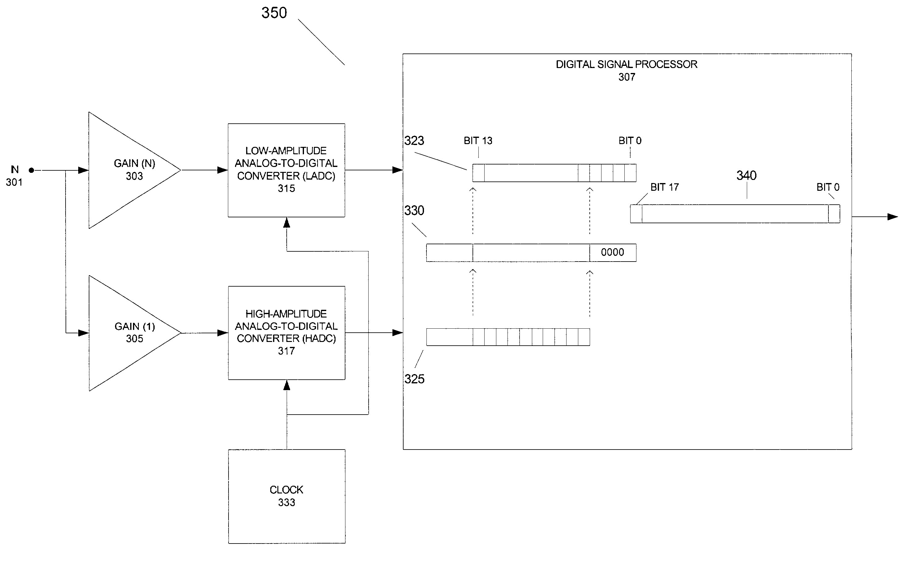
[0020]In another approach, an even better performance is obtained with the use of two identical analog-to-digital converters (ADCs) operating from a single clock. One of the two ADC inputs may be preceded ...


PUM


Abstract

An improved analog-to-digital converter device suitable for use in digital hearing aids, and methods for operating such a device are disclosed. Aspects of the present invention may provide a full 16–18 bits (96–108 dB) of dynamic range in a digital hearing aid circuit using 14-bit analog-to-digital converters typically available for hearing aid use. An embodiment of the present invention may use two analog-to-digital converters that are clocked by the same sampling trigger. One of the converters may be preceded by an amplifier having, for example, 24 dB of gain, while the other converter may be preceded by an amplifier having 0 dB of gain. The output of the first converter or the output of the second converter may be used, or a combination of the two outputs may be used to produce audio for the hearing aid user, depending upon input signal level.

Description

RELATED APPLICATIONS[0001]The applicants claim priority based on provisional application Ser. No. 60 / 332,817, “Improved Dynamic Range Analog to Digital Converter Suitable for Hearing Aid Applications”, filed Nov. 15, 2001, the complete subject matter of which is incorporated herein by reference in its entirety.FEDERALLY SPONSORED RESEARCH OR DEVELOPMENT[0002][Not Applicable]MICROFICHE / COPYRIGHT REFERENCE[0003][Not Applicable]BACKGROUND OF THE INVENTION[0004]The introduction of digital signal processing to hearing aids provided greater flexibility than had been previously available. In the initial excitement, many of the digital hearing aids, which often sold for $2000–$3000 each, were advertised as “CD quality.” In fact, most had only a 6–7 kHz bandwidth, and instead of the 96 dB dynamic range of compact discs, they had only 80–84 dB dynamic range. The first inventor has listened to virtually all the available digital hearing aids over the years, and found that as a result of their ...

Claims


Application Information

Patent Timeline
Patent Type & Authority Patents(United States)
IPC IPC(8): H04R25/00
CPCH04R25/505H03M1/188
Inventor KILLION, MEAD C.MAPES-RIORDAN, DAN
Owner ETYMOTIC RES
Why Eureka
Try Eureka