Optical switch with moveable holographic optical element

a technology of optical switches and holographic elements, applied in the field of optical elements, can solve the problems of difficult mass production, complex optical systems, and limited use of hoists as optical switches

Inactive Publication Date: 2006-02-21
ROSEMOUNT INC
View PDF118 Cites 98 Cited by
  • Summary
  • Abstract
  • Description
  • Claims
  • Application Information

AI Technical Summary

Problems solved by technology

One disadvantage is that because diffractive optics structures are formed of patterns of diffracting elements they are sensitive to the wavelength of the light used.
Further, as HOEs are planar devices, complex optical systems may be assembled in a simplified manner using less space than typical multi-element optical systems.
Current designs of HOE

Method used


Image

  • Optical switch with moveable holographic optical element
  • Optical switch with moveable holographic optical element
  • Optical switch with moveable holographic optical element

Examples


Embodiment Construction

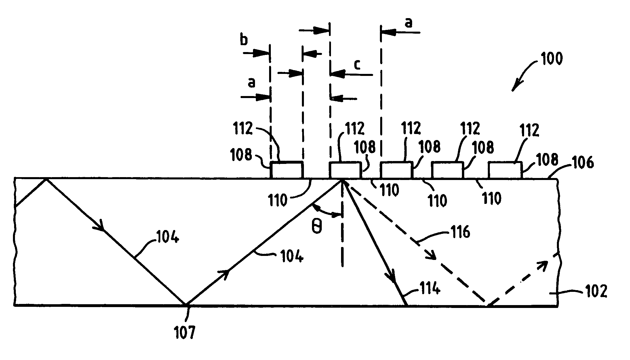
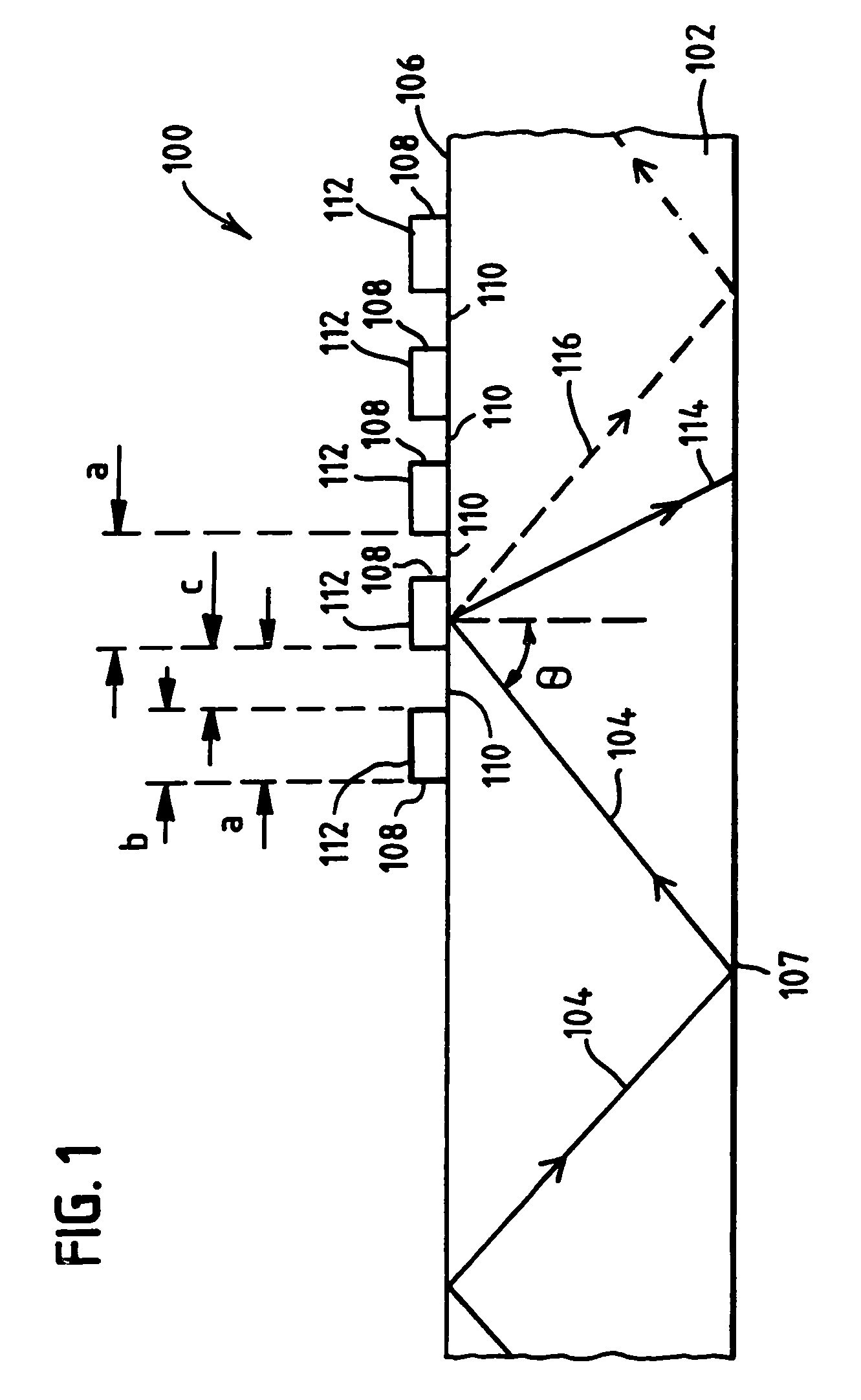
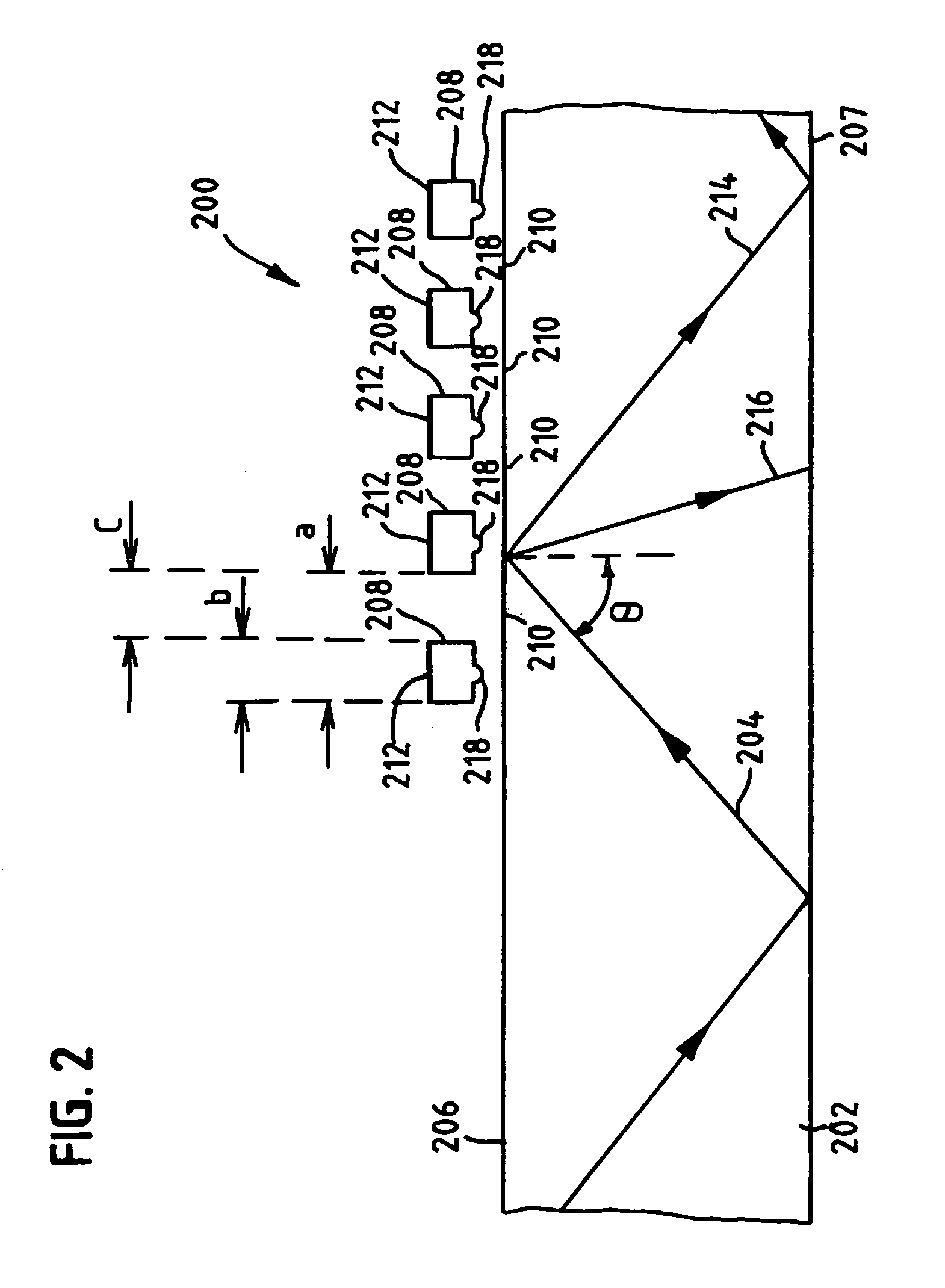
[0028]The present disclosure solves the above-described problems by providing a HOE that is easily fabricated and usable with an optical substrate to form an optical switch. Preferably, the HOEs described hereinbelow are grating structures that are moveable relative to an optical substrate within which a light signal travels. The movement of the HOE functions to couple and decouple the HOE with the substrate, so that if a light signal is traveling in the substrate the HOE may selectively interact with the light signal. For maximum efficiency, light is made to travel in the optical substrate under total internal reflection (TIR), which as will be understood includes a range of propagation paths of the light traveling in the substrate. Total internal reflection is a well known phenomena that allows light to be reflected from the interface between two optical materials without losses. This occurs if light is propagating in a material with a higher refractive index than a surrounding op...


PUM


Abstract

An optical switch formed of a holographic optical element (HOE) disposed above a top surface of a substrate and moveable relative thereto is shown. Light is traveling through the substrate under total internal reflection, which creates an evanescent field extending beyond the reflecting surfaces of the substrate. The HOE is characterized, in one embodiment, by being formed from a plurality of strips that are moveable between a first position in which the strips are above the evanescent field and a second position in which the strips are inside the evanescent field. In the first position, the light in the substrate propagates unaffected by the HOE in a primary direction of propagation. In the second position, the light in the substrate is altered by the HOE and made to propagate in a reflected direction oblique to that of the primary direction of propagation.

Description

CROSS-REFERENCE TO RELATED APPLICATIONS[0001]This application claims the benefit of U.S. Provisional Application No. 60 / 223,503, filed Aug. 7, 2000, U.S. Provisional Application No. 60 / 223,508 filed Aug. 7, 2000, and U.S. Provisional Application No. 60 / 271,103 filed Feb. 23, 2001.FIELD OF THE INVENTION[0002]The present invention relates generally to optical elements and more specifically to optical gratings and holographic optical elements used to perform optical switching functions.BACKGROUND OF THE PRIOR ART[0003]Diffractive optics using optical elements that affect propagating wavefronts by means of diffraction are known. Exemplary diffractive optical element (DOE) structures are diffraction gratings, zone plate lens and holographic mirrors. DOEs in which the diffracting element sizes are approaching or approximately equal to the wavelength of light are generally known as holographic optical elements (HOEs). One advantage to diffractive optics is that a structure, such as a DOE l...

Claims


Application Information

Patent Timeline
IPC IPC(8): G02B6/26G02B6/34G02B6/42G02B6/124G02B6/35
CPCG02B6/124G02B6/3536G02B6/3534G02B6/4214G02B6/357G02B6/3584G02B6/3548
Inventor FRICK, ROGER L.WILLCOX, CHARLES R.
Owner ROSEMOUNT INC
Why Eureka
Try Eureka