Electronic component cooling system for an air-cooled chiller

a cooling system and electronic component technology, applied in the field of electronic component cooling system, can solve the problems of undesirable condensation, large heat generation of electronic components of chiller system, and condensation of enclosures, so as to reduce the number of components and prevent condensation

Active Publication Date: 2006-02-28
JOHNSON CONTROLS TYCO IP HLDG LLP
View PDF42 Cites 62 Cited by
  • Summary
  • Abstract
  • Description
  • Claims
  • Application Information

AI Technical Summary

Benefits of technology

[0007]One advantage of the present invention is a reduction of the number of components, as the cooling system for the power / control panel is incorporated into the chiller system.
[0008]Another advantage of the present invention is that it substantially prevents the formation of condensation in the power / control panel.
[0009]Still another advantage of the present invention is that it does not require a separate temperature monitoring and control system.

Problems solved by technology

Electrical components associated with the electronic powering of a chiller system generate a great deal of heat in operation.
However, condensation may form inside the enclosure when the temperature of the working fluid in the heat transfer fluid loop is less than the dew point temperature inside the cabinet.
Condensation is undesirable, as it can damage the electrical components.

Method used


Image

  • Electronic component cooling system for an air-cooled chiller
  • Electronic component cooling system for an air-cooled chiller
  • Electronic component cooling system for an air-cooled chiller

Examples


Embodiment Construction

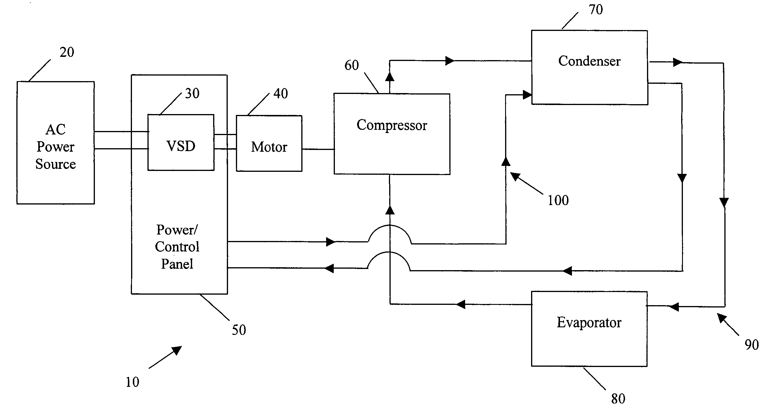
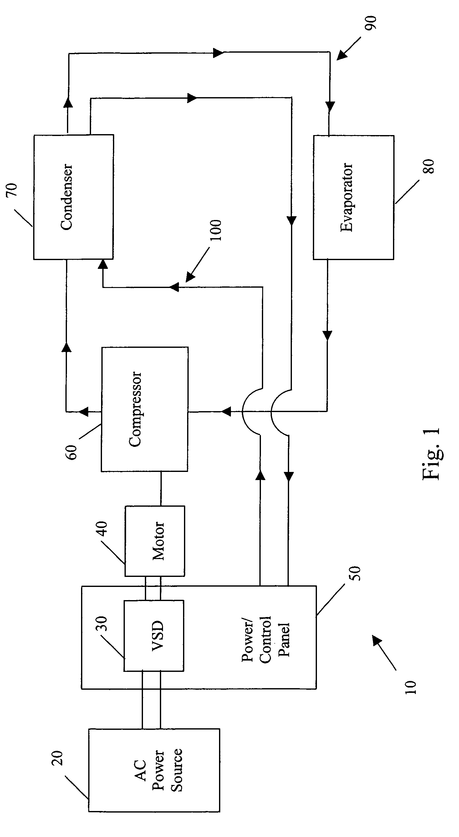
[0017]FIG. 1 illustrates generally the system configuration of the present invention. A chiller system 10 includes an AC power source 20 that supplies a combination variable speed drive (VSD) 30 and power / control panel 50, which powers a motor 40 that drives a compressor 60, as controlled by the controls located within the power / control panel 50. In one embodiment of the invention, all of the components of the VSD 30 are contained within the power / control panel 50. The AC power source 20 provides single phase or multi-phase (e.g., three phase), fixed voltage, and fixed frequency AC power to the VSD 30 from an AC power grid or distribution system that is present at a site. The compressor 60, condenser 70 and evaporator 80 define a first closed refrigerant loop 90. The compressor 60 compresses a refrigerant vapor and delivers the vapor to the condenser 70 through a discharge line. The compressor 60 can be any suitable type of compressor, e.g., centrifugal compressor, reciprocating com...


PUM


Abstract

A chiller system includes a refrigerant loop, the refrigerant loop further including a compressor, an air-cooled condenser arrangement and an evaporator arrangement connected in a first closed refrigerant loop. A motor is connected to the compressor to drive the compressor, a drive is connected to the motor to power the motor and a power / control panel controls the refrigerant loop. The power / control panel and the condenser arrangement are connected in a second closed coolant loop. The second closed coolant loop provides cooling to the enclosure and / or components within the enclosure disposed on a chill plate. Condensation is substantially prevented from forming inside the enclosure, despite the enclosure lacking a humidity control device.

Description

BACKGROUND OF THE INVENTION[0001]The present invention relates generally an electronic component cooling system. More specifically, the present invention relates to a cooling system for electronic power and / or control components of an air-cooled chiller system.[0002]Electrical components associated with the electronic powering of a chiller system generate a great deal of heat in operation. Since these components are typically housed in a compact enclosure that is substantially sealed against exposure to the elements, the heat generated within the enclosure by the power electronic components must be dissipated to avoid damaging the components. Power electronic semi-conductor components in the enclosure that generate especially large amounts of heat during operation are typically cooled using a chill plate. The chill plate is composed of a material having high thermal conductivity and includes internal channels, which constitute a portion of a heat transfer fluid loop that circulates ...

Claims


Application Information

Patent Timeline
Patent Type & Authority Patents(United States)
IPC IPC(8): F25D23/12F25B23/00F25B31/00F25B39/04F28D1/04F28D1/047
CPCF25B31/006F25B39/04F28D1/0426F28D1/0477Y02B30/741F25B2600/021Y02B30/70F25B31/00F25D17/00F25D23/12
Inventor KESTER, DOUGLAS ALANSCHNETZKA, HAROLD ROBERTYANIK, MUSTAFA KEMELJUDGE, JOHN F.NADUVATH, MAHESH VALIYAHILL, IV, FRANK HIGHLAND
Owner JOHNSON CONTROLS TYCO IP HLDG LLP
Why Eureka
Try Eureka