
Shallow metallic s-seal

a metallic seal and thin layer technology, applied in the direction of fluid pressure sealing joints, engine seals, flanged joints, etc., can solve the problems of plastic deformation of the mating surface of the member, the resiliency of this type of seal is rather limited, and the basic “c” seals typically cannot reach the desirable standard vacuum level of 110e, etc., to achieve high reliability and low cost of manufacture

Inactive Publication Date: 2006-02-28
EATON INTELLIGENT POWER LTD
View PDF26 Cites 19 Cited by
  • Summary
  • Abstract
  • Description
  • Claims
  • Application Information

AI Technical Summary

Benefits of technology

[0011]One object of the present invention is to provide a highly reliable metallic seal that is relatively inexpensive to manufacture.
[0012]Another object of the present invention is to provide a metallic seal, which has geometrically simple cross sections, and can be manufactured with existing equipment in large quantities with tight tolerances.
[0013]Still another object of the present invention is to provide a highly reliable metallic seal, which concentrates the available load over a narrow band which minimizes the required load to compress the seal by optimizing the sealing dam width.
[0014]Yet another object of the present invention is to provide a metallic seal in which the seal dam does not significantly shift during compression of the seal.

Problems solved by technology

One problem with a solid metal ring is that the force created could be of sufficient magnitude to cause plastic deformation of the mating surfaces of the members.
However, the resiliency of this type of seal is rather limited because the “O” ring, whether solid or hollow, is usually too stiff, and is inherently expensive.
However, the basic “C” seals typically cannot reach the desirable standard vacuum level of 1×10e−9 cc / sec He leakage rate or better without modification and without being coated with very soft plating materials.

Method used


Image

  • Shallow metallic s-seal
  • Shallow metallic s-seal
  • Shallow metallic s-seal

Examples


Embodiment Construction

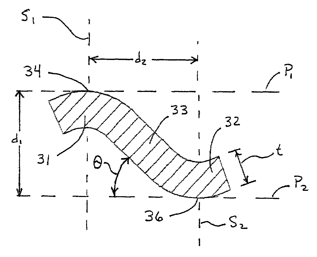
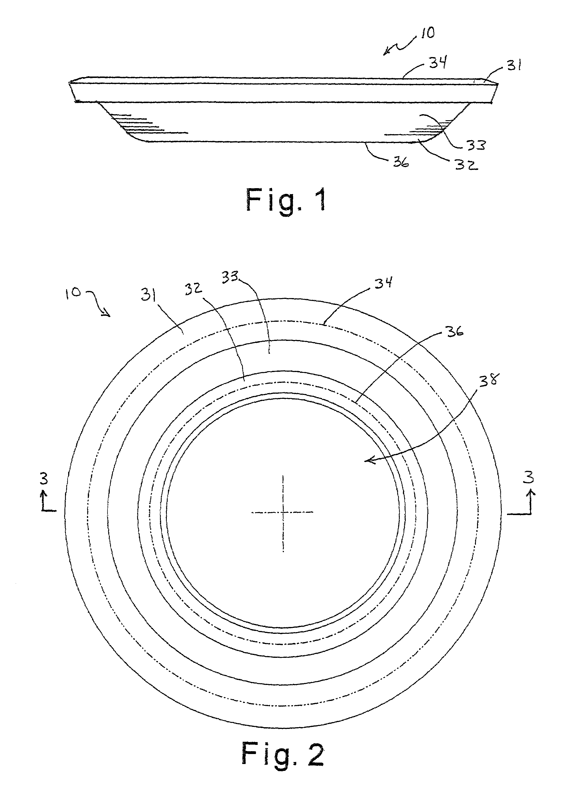
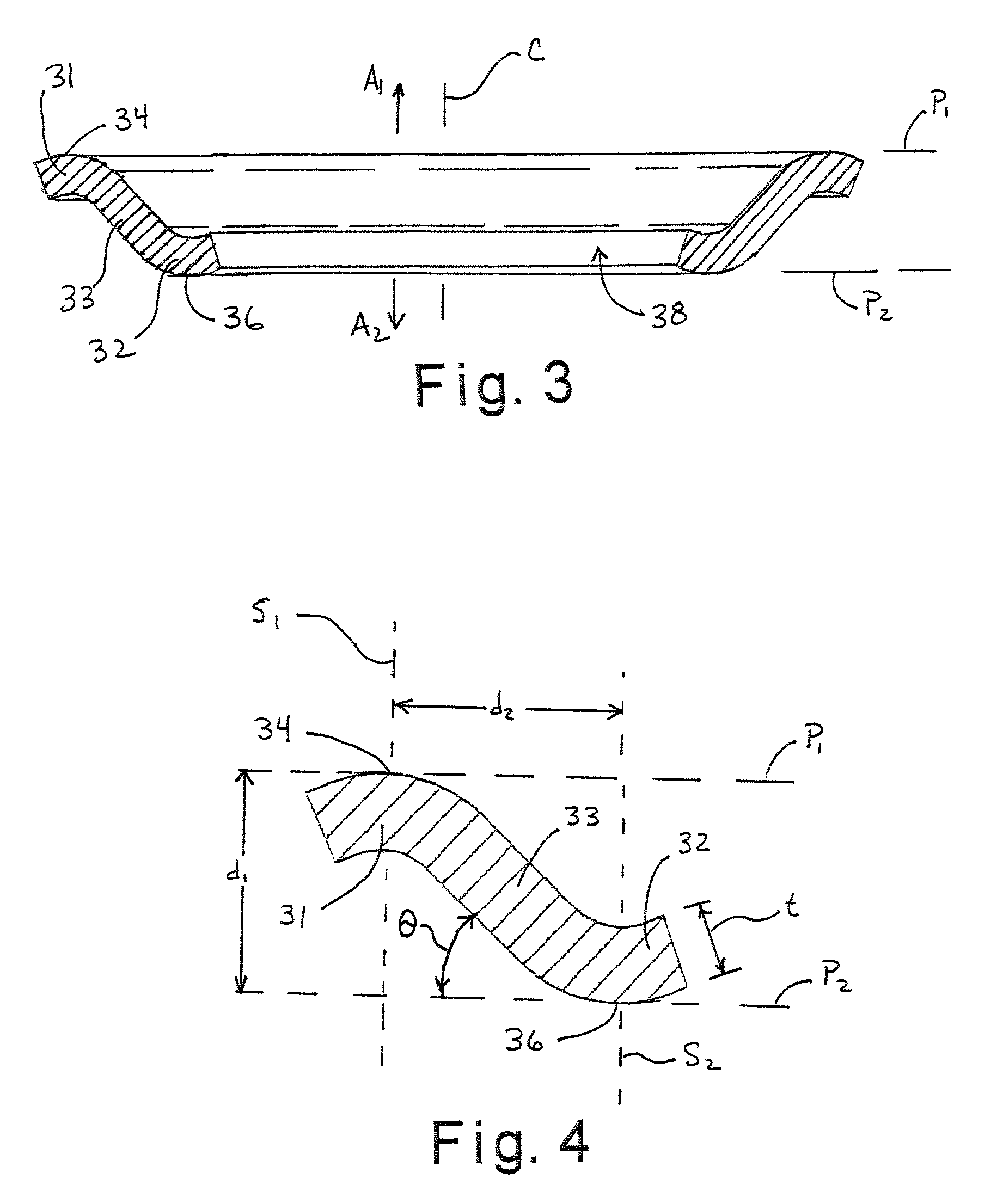
[0026]Initially referring to FIGS. 1–4, a shallow metallic seal 10 in accordance with a first embodiment of the present invention is illustrated. The shallow metallic seal 10 is illustrated as being circular. However, it will be apparent to those skilled in the art from this disclosure that the shallow metallic seal 10 could have other types of non-circular ring shapes and can also be produced in a variety of heights. Moreover, the thickness of the metallic seal 10 in the attached drawings has been exaggerated for purposes of illustration.

[0027]The purpose of the metallic seal 10 is to provide a seal between two opposing members, e.g., either metal to metal, metal to ceramic, ceramic to ceramic, or any appropriate combination of materials commonly used in critical fluid and / or gas sealing. Additionally, the metallic seal 10 can be used between flanges or components for any fluid control or pneumatic application. The metallic seal 10 will most typically be used in a groove, counterbo...


PUM


Abstract

A metallic seal is provided that concentrates the available load over a narrow band to produce a sealing dam over a sufficient width to minimize leakage on a molecular level. The metallic seal has a first annular end section with has a first annular sealing surface, a second annular end section with a second annular sealing surface and an annular center section extending between the first and second annular end sections to form a ring having a central passageway with a center longitudinal axis. The third annular section is frustoconical tube with the first and second annular end sections being contiguously arranged at opposite ends of the annular center section such that sealing loads applied substantially perpendicularly on the first and second annular sealing surfaces primarily deform due to torsional stress of the metallic seal.

Description

BACKGROUND OF THE INVENTION[0001]1. Field of the Invention[0002]This invention generally relates to a metallic seal for creating a seal between a pair of members. More specifically, the present invention relates to a seal that provides a highly reliable seal by concentrating the available load over a narrow band (small sealing area equaling high contact stress) to produce a high quality sealing dam over a sufficient width to minimize leakage on a molecular level.[0003]2. Background Information[0004]A typical static seal assembly has a first member with a first mating surface, an annular seal of suitable sealing material (e.g., metal O-ring), and a second member with a second mating surface. A mechanical load is applied to the seal through the first and second mating surfaces of the members. Typically, the mechanical load is created by torquing down a multitude of fasteners such that a displacement, also known as compression, occurs between the sealing surfaces. The net loading of th...

Claims


Application Information

Patent Timeline
Patent Type & Authority Patents(United States)
IPC IPC(8): F16J15/02F16J15/08F16L23/20
CPCF16L23/20F16J15/0887
Inventor SPENCE, JOHN LOYDROWLAND, STEPHEN B.
Owner EATON INTELLIGENT POWER LTD
Learn More