
Cabled connector including cable guide attached detachably to connector cover

a cable guide and connector technology, applied in the direction of coupling device connection, coupling/disconnecting parts engagement/disengagement, electrical apparatus, etc., can solve the problems of insufficient emi measures for the connector structure, and the possibility of electrical wave generated in the connector to leak out of the connector

Inactive Publication Date: 2006-02-28
FUJITSU COMPONENENT LTD
View PDF8 Cites 7 Cited by
  • Summary
  • Abstract
  • Description
  • Claims
  • Application Information

AI Technical Summary

Benefits of technology

[0014]A more specific object of the present invention is to provide a cabled connector which can adapt to miniaturization, facilitate assembly, and easily deal with differences in diameter of the cable and differences in angle at which the cable is drawn out.
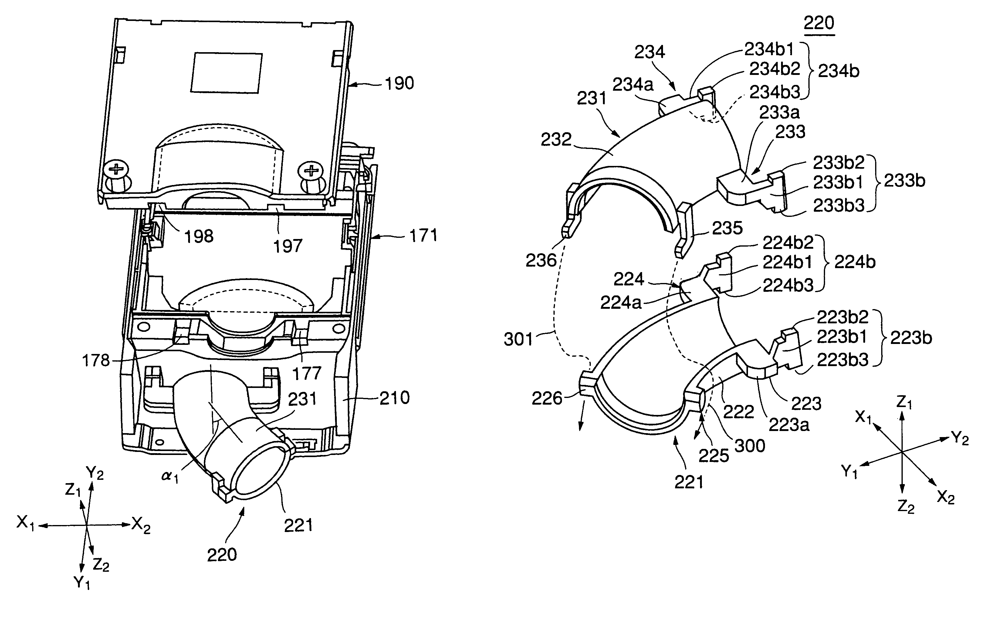
[0018]According to the present invention, the two cable half guides can be coupled at the end parts without using a screw. At the base parts, the two cable half guides are coupled to form the cable guide and attached detachably to the connector cover, in the course of coupling the first half cover and the second half cover. Thereby, it becomes unnecessary to only couple the two cable half guides, or to only attach the cable guide to the connector cover. Thus, the cabled connector can be assembled easily.
[0020]According to the present invention, simply by attaching the cable guide in a different direction, the cabled connector can be connected properly to a variously directed opponent connector.
[0022]According to the present invention, the receding portions formed limitedly within the respective widths of the wall portions are used for engaging the portion of the cable guide at the base part. Therefore, even when the cable guide is not attached, since the receding portions for engaging the portion of the cable guide do not reach an inside part of the connector, the connector cover still exhibits an excellent shielding property.

Problems solved by technology

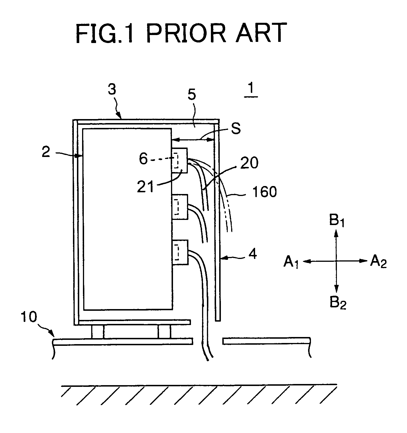
Besides, when a transmission rate of data is as high as 1 Gbit per second, a signal wavelength becomes short so that an electromagnetic wave generated in the connector becomes likely to leak out of the connector.
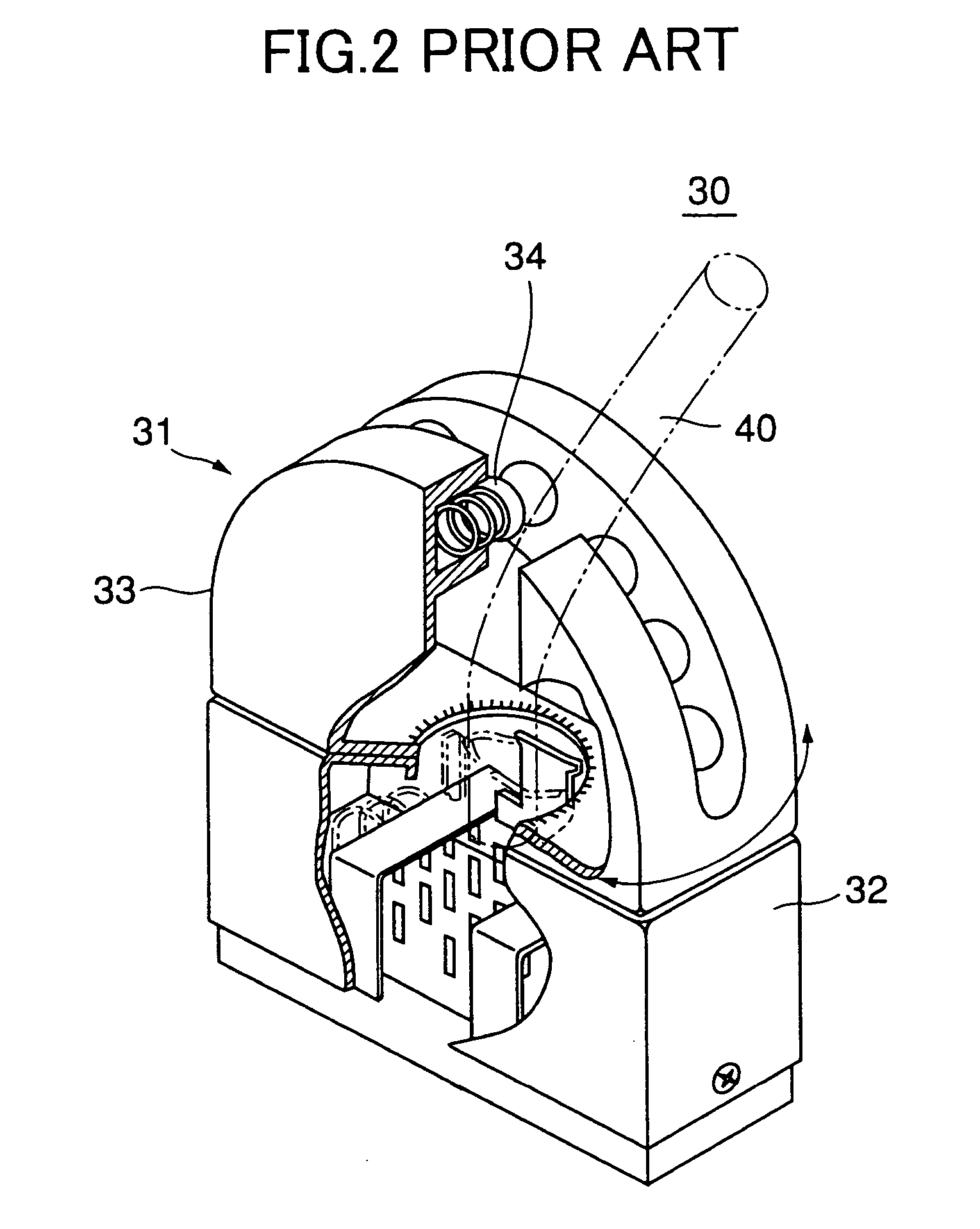
However, EMI measures are not sufficiently taken for the structure of the connector 30.

Method used


Image

  • Cabled connector including cable guide attached detachably to connector cover
  • Cabled connector including cable guide attached detachably to connector cover
  • Cabled connector including cable guide attached detachably to connector cover

Examples


Embodiment Construction

[0043]A description will now be given, with reference to the drawings, of embodiments according to the present invention.

[0044]FIG. 3 is a perspective rear view of a balanced transmission connector 100 with a balanced transmission cable according to an embodiment of the present invention. FIG. 4 is an exploded perspective front view of the balanced transmission connector 100. FIG. 5 is a cross-sectional view taken along a line V—V in FIG. 3. The balanced transmission connector 100 is provided on an end of the balanced transmission cable 160. That is, the balanced transmission cable 160 extends from a backside of the balanced transmission connector 100. X1–X2 indicates a width direction of the connector 100; Y1–Y2 indicates a longitudinal direction of the connector 100; and Z1–Z2 indicates a height direction of the connector 100.

[0045]As shown in FIG. 3, FIG. 4 and FIG. 5, the connector 100 comprises a balanced transmission plug body 120, and a repeating substrate 140 soldered and fi...


PUM


Abstract

A connector cover is formed by combining a first half cover and a second half cover. A cable guide is formed to have a pipe form by combining two cable half guides each having a semicircular cross section. The cable guide envelopes and guides a part of a cable leading out from the connector cover. The two cable half guides are coupled by being engaged with each other at one end, and are coupled with each other and attached detachably to the connector cover by being held between the first half cover and the second half cover at the other end.

Description

BACKGROUND OF THE INVENTION[0001]1. Field of the Invention[0002]The present invention generally relates to a cabled connector, and more particularly, to a balanced transmission connector with a balanced transmission cable which is used for connection between parts performing a balanced transmission of data, such as connection between a computer and a server.[0003]A cabled connector is provided with a cable extending from a backside. A balanced transmission connector with a balanced transmission cable includes multiple terminals arranged suitably for a balanced transmission, in which the balanced transmission cable extends from a backside of the balanced transmission connector.[0004]Methods of transmitting data between a computer and a server include a common transmission method using one wire for each data, and a balanced transmission method using a pair of wires for each data so as to transmit a +signal, which is originally to be transmitted, and simultaneously, a −signal reversed ...

Claims


Application Information

Patent Timeline
IPC IPC(8): H01R13/62H01R13/56H01R13/58
CPCH01R13/562H01R13/5841Y10S439/906
Inventor KUMAMOTO, TADASHIKOBAYASHI, MITSURUMIYAZAWA, HIDEO
Owner FUJITSU COMPONENENT LTD
Learn More