Ionization apparatus

a technology of ionization apparatus and ionization ring, which is applied in the direction of particle separator tube details, instruments, separation processes, etc., can solve the problems of drop in detection sensitivity, and inability to restore the function of the apparatus, so as to reduce the number of components, reduce the space taken up by the apparatus, and restore the effect of the apparatus before deterioration of the function

Inactive Publication Date: 2006-02-28
ANELVA CORP
View PDF19 Cites 21 Cited by
  • Summary
  • Abstract
  • Description
  • Claims
  • Application Information

AI Technical Summary

Benefits of technology

[0031]By making use of components used in the ionization process for the plasma generation mechanism and the plasma pull-in electrode, it is possible to reduce the number of components and reduce the space taken up by the apparatus.
[0032]In the ionization apparatus, the ionization process and the process of cleaning away the by-products using plasma are preferably performed consecutively. The plasma should be generated in the ionization zone right before measurement by mass spectrometry of the sample gas or right after that measurement. By this, even when measuring a qualitatively or quantitatively different target gas in the preceding or succeeding mass spectrometry measurement, the gas remaining in the ionization apparatus or the deposits on the components are removed and the interval until the next accurate measurement by mass spectrometry becomes shorter. Further, it is possible to completely restore the function of the apparatus before deterioration of the function progresses.
[0033]The gas introduced into the ionization zone at the time of generation of plasma is made oxygen. This is because by-products deposited due to ionization can be easily removed by oxygen when for example the target gas includes a gaseous state organic substance. Further, when removing deposits on the ion emitter by plasma, the surface of the ion emitter is also slightly etched. The ion emitter does not emit a sufficient amount of metal ions in a state not oxidized. Therefore, using oxygen as the gas for causing generation of plasma in the ionization zone is suitable for removal of deposits comprised of organic substances and can cause oxidation of the surface of the ion emitter while removing the deposits when removing them on...

Problems solved by technology

As a result of the buildup, the problems arise of a drop in the amount of emission of the metal ions, a detrimental effect on the transport of ions required for measurement, etc. and therefore a drop in the detection sensitivity.
This restoration is not always effective depending on the type of the target gas.
These solid substances will enter into the mass spectrometry apparatus with its complicated and precise structure and make accur...

Method used


Image

  • Ionization apparatus
  • Ionization apparatus
  • Ionization apparatus

Examples


first embodiment

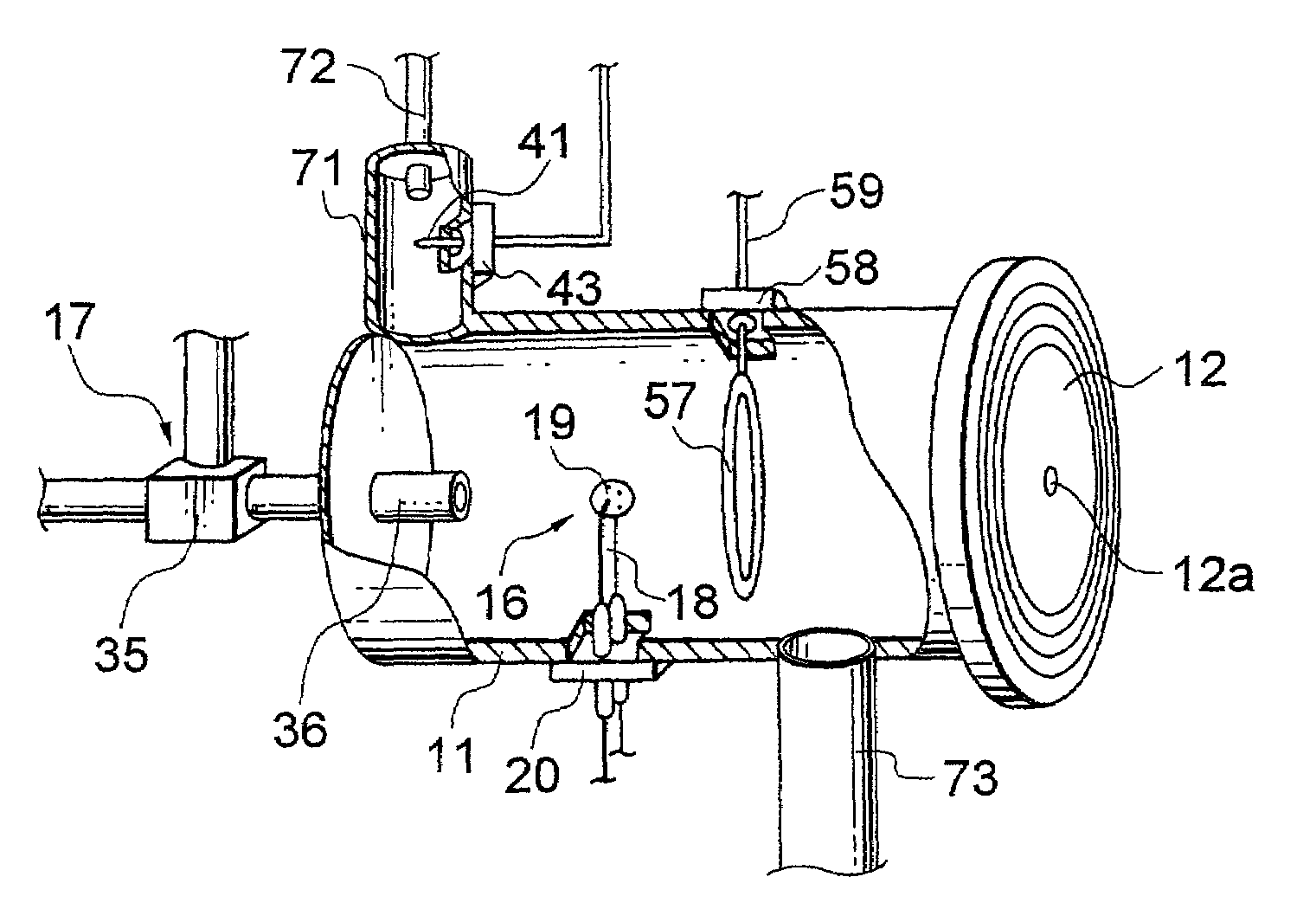
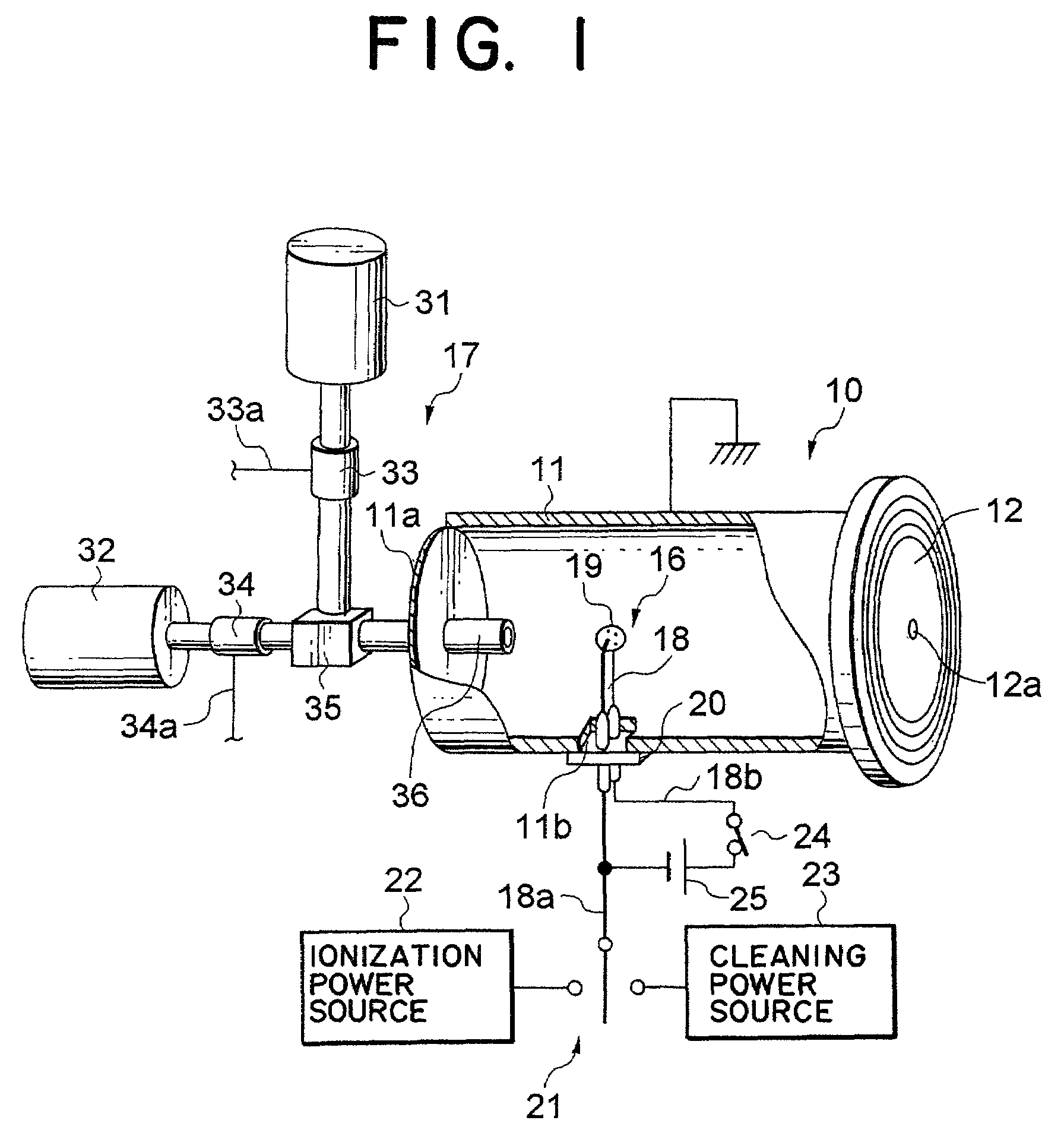
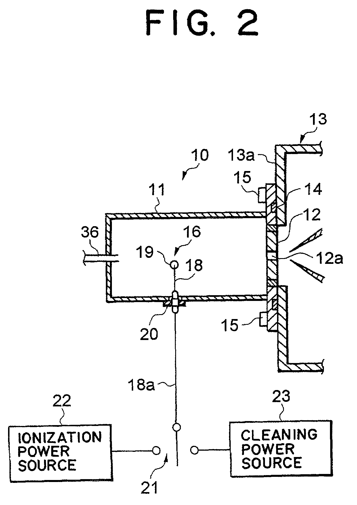
[0051]the present invention will be explained with reference to FIG. 1 and FIG. 2. FIG. 1 is a perspective view of an ionization apparatus partially cut away to show the principal structure inside, while FIG. 2 is a longitudinal sectional view of the same. In this embodiment, the example is shown where the ion emitter for emitting metal ions for ionization is also used as an electrode at the time of cleaning.

[0052]As shown in the figures, the ionization apparatus 10 has a closed-end cylindrically shaped hollow vessel 11 formed by a metal material. In this embodiment, the hollow vessel 11 is grounded and held at the ground potential (zero potential). At the left end surface of the hollow vessel 11 in the figure is formed the bottom 11a. At the right end side in the figure is affixed a disk-shaped screen 12 having an aperture 12a at its center. As shown in FIG. 2, the hollow vessel 11 is connected to a mass spectrometry apparatus 13 through the screen 12. Between the screen 12 and the...

second embodiment

[0067]Further, in the second embodiment, the potential of the hollow vessel 11, the potential of the ion emitter 19, and the potentials of the other components inside may be freely set by a not shown power source.

[0068]In the configuration of this embodiment, the ion emitter 16 is used only for the ion attachment ionization process. Only the above-mentioned ionization power source 22 is connected to the outside end 18a of the lead wire 18 of the ion emission mechanism 16. At the time of the ionization process, the electrode 41 has no function at all. On the other hand, when causing discharge at the ionization zone to produce plasma for a cleaning action, the needle shaped electrode 41 is supplied with predetermined power from the above-mentioned cleaning power source 23.

[0069]In the ionization apparatus according to the second embodiment, as explained above, the target gas and third-body gas are simultaneously introduced from the gas introduction pipe member 36 under the pressure co...

third embodiment

[0073]The third embodiment is an ionization apparatus having a structure for preventing contact between the ion emitter 19 and the target gas and enabling stable, sufficient amount of emission of metal ions from the ion emitter 19 over a long period. Therefore, in the hollow vessel 11, the target gas introduction mechanism and the third-body gas introduction mechanism are provided independently. In FIG. 7, 51 designates a third-body gas introduction pipe, while 52 designates a target gas introduction pipe. The target gas introduction pipe 52 is attached through an insulator 52a. The target gas introduction mechanism and the third-body gas introduction mechanism are not illustrated, but conventional well known mechanisms are used. Further, the metal ion generation zone 53 arranged in the ion emission mechanism 16 and the ionization zone 54 where the target gas is introduced to are separated by the screen 55 leaving only the aperture 55a through which the metal ions pass. The ionizati...


PUM


Abstract

An ionization apparatus according to the present invention has a mechanism for causing metal ions emitted from an ion emitter to attach to an introduced target gas so as to generate ions of the sample gas and emits the ions of the sample gas to a mass spectrometer. The mass spectrometer has a zone in which one or both of an electric field and magnetic field are formed. As the electrode for causing the generation of cleaning plasma in the ionization zone generating the ions of the sample gas, the ion emitter is used. The ion emitter causes the generation of plasma in connection with a hollow vessel and removes deposits on components facing the ionization zone by the plasma. The plasma cleaning process is performed consecutively at a suitable timing after the ionization process. Due to the above configuration, deteriorated performance in ionization can be restored in a short time, a memory effect can be prevented, and accurate mass spectrometry becomes possible. The ionization apparatus of the present invention is suitable for a mass spectrometry apparatus.

Description

BACKGROUND OF THE INVENTION[0001]1. Field of the Invention[0002]The present invention relates to an ionization apparatus, more particularly relates to an ionization apparatus using ion attachment ionization and suitable for mass spectrometry of a target gas including a gaseous state organic substance, chemically active substance, or highly adsorptive substance.[0003]2. Description of the Related Art[0004]As for the mass spectrometry of various types of gases there are conventional mass spectrometry methods of ionizing a target gas to make ions, then separating and analyzing the ions by mass using one or both of an electric field and a magnetic field. There are various methods for ionization of the target gas. Among these, the ion attachment ionization method has the feature of a lower excess energy at the time of ionization than other methods of ionization. In this ion attachment ionization method, the target gas is defined as a gas being a target substance for analysis, while a sam...

Claims


Application Information

Patent Timeline
IPC IPC(8): H01J49/00G01N27/62G01N27/68H01J49/04H01J49/10
CPCH01J49/04
Inventor SHIOKAWA, YOSHIRONAKAMURA, MEGUMISASAKI, TOHRUFUJII, TOSHIHIRO
Owner ANELVA CORP
Why Eureka
Try Eureka