Electrodynamic apparatus and method of manufacture

a technology of electrodynamic apparatus and manufacturing method, which is applied in the direction of dynamo-electric components, mechanical energy handling, synchronous machines with stationary armatures and rotating magnets, etc., can solve the problems of unreliable and impractical time domain multiphase switching, unreliable electric motors initially utilized for these drives, and low efficiency of electric motors. , to achieve the effect of minimizing thickness and reducing tooling costs

Inactive Publication Date: 2006-02-28
PETERSEN TECH
View PDF12 Cites 28 Cited by
  • Summary
  • Abstract
  • Description
  • Claims
  • Application Information

AI Technical Summary

Benefits of technology

[0014]The present invention is addressed to electrodynamic apparatus and a method of manufacturing the stator core assemblies thereof utilizing pressed powder technologies wherein requisite stator core material densities are achieved while part thicknesses and volumes are retained within desirable dimensional limits. Requisite ratios of component widths or thicknesses to corresponding lengths are maintained in proper combinations while minimizing thicknesses of core structures through the employment of two or more stator core modules or components which, following their press forming, are selectively combined to define a sequence of module core components over which field windings are positioned. Because the stator core modules may be geometrically identical, tooling costs may be conserved through employment, in effect, of a single mold to produce them.
[0015]In one embodiment of the invention, paired stator core modules are combined in tandem along the axis of the electrodynamic apparatus to achieve an enhanced functional capacity while minimizing the diametric extent of the device within which they perform. With this arrangement, two or more sets of phase defining field windings are utilized with wire diameters of smaller extent. These phase defining windings advantageously then may be combined for simultaneous excitation through employment of a series or parallel electrical interconnection.

Problems solved by technology

With progress in these fields, classically designed electric motors, for example, utilizing brush-based commutation, have been found to be unacceptable or, at best, marginal performers.
The electric motors initially utilized for these drives were relatively expensive and incorporated a variety of refinements, for instance as necessitated with the introduction of rotating disc memory.
By contrast, simple, time domain-based multiphase switching has been considered to be unreliable and impractical since the rotation of the rotor varies in terms of speed under load as well as in consequence of a variety of environ mental conditions.
The high promise of pressed powder components for motors and generators initially was considered compromised by a characteristic of the material wherein it exhibits relatively low permeability.
This necessarily has lead to a concomitant call for larger press molded structures.
Thus as the length of stator core component structures increase, their thickness must increase to an extent that a resultant shape becomes so enlarged in widthwise cross section as to defeat the design goal, with attendant loss of both the economies of cost and enhanced performance associated with this emerging pressed powder technology.

Method used


Image

  • Electrodynamic apparatus and method of manufacture
  • Electrodynamic apparatus and method of manufacture
  • Electrodynamic apparatus and method of manufacture

Examples


Embodiment Construction

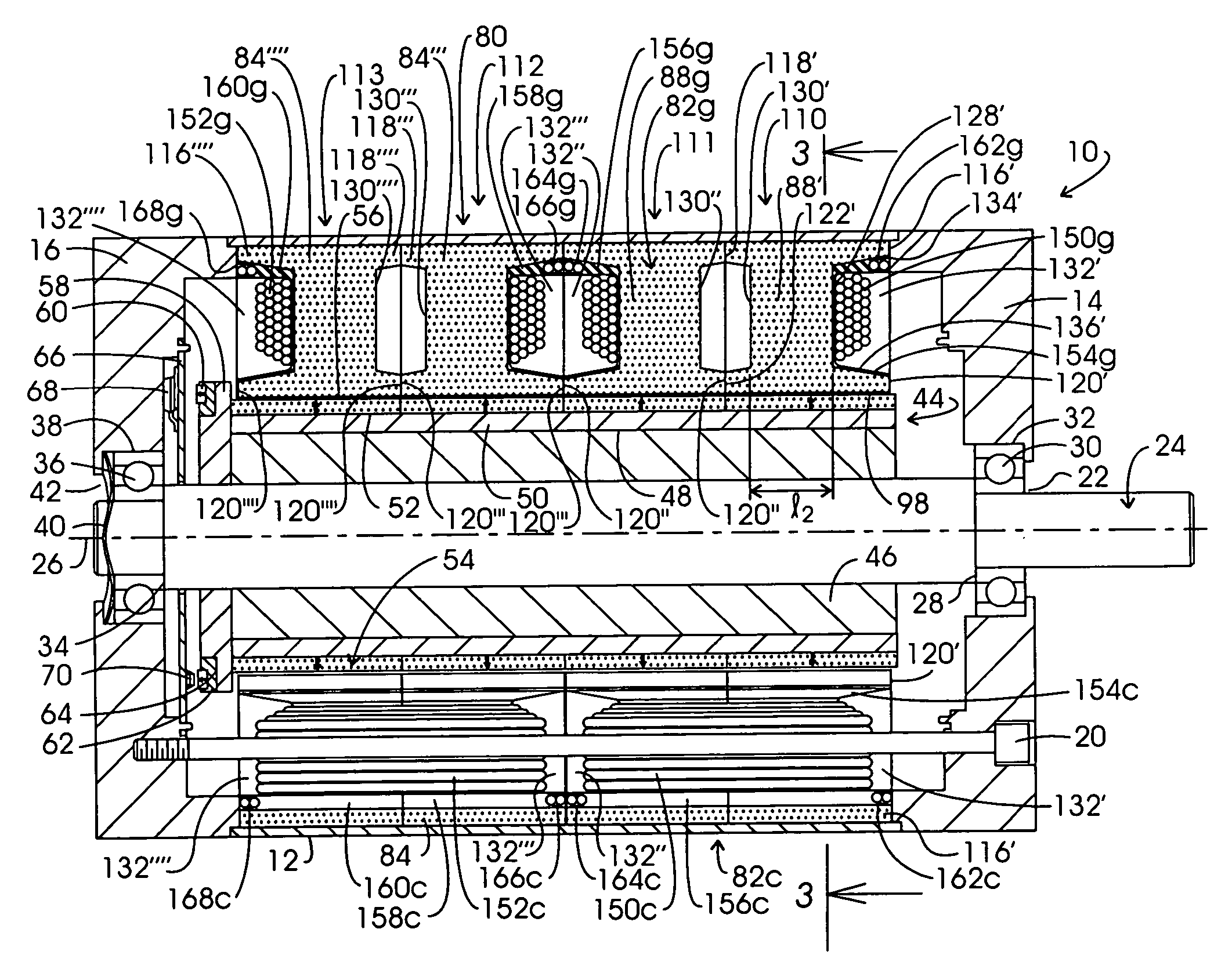
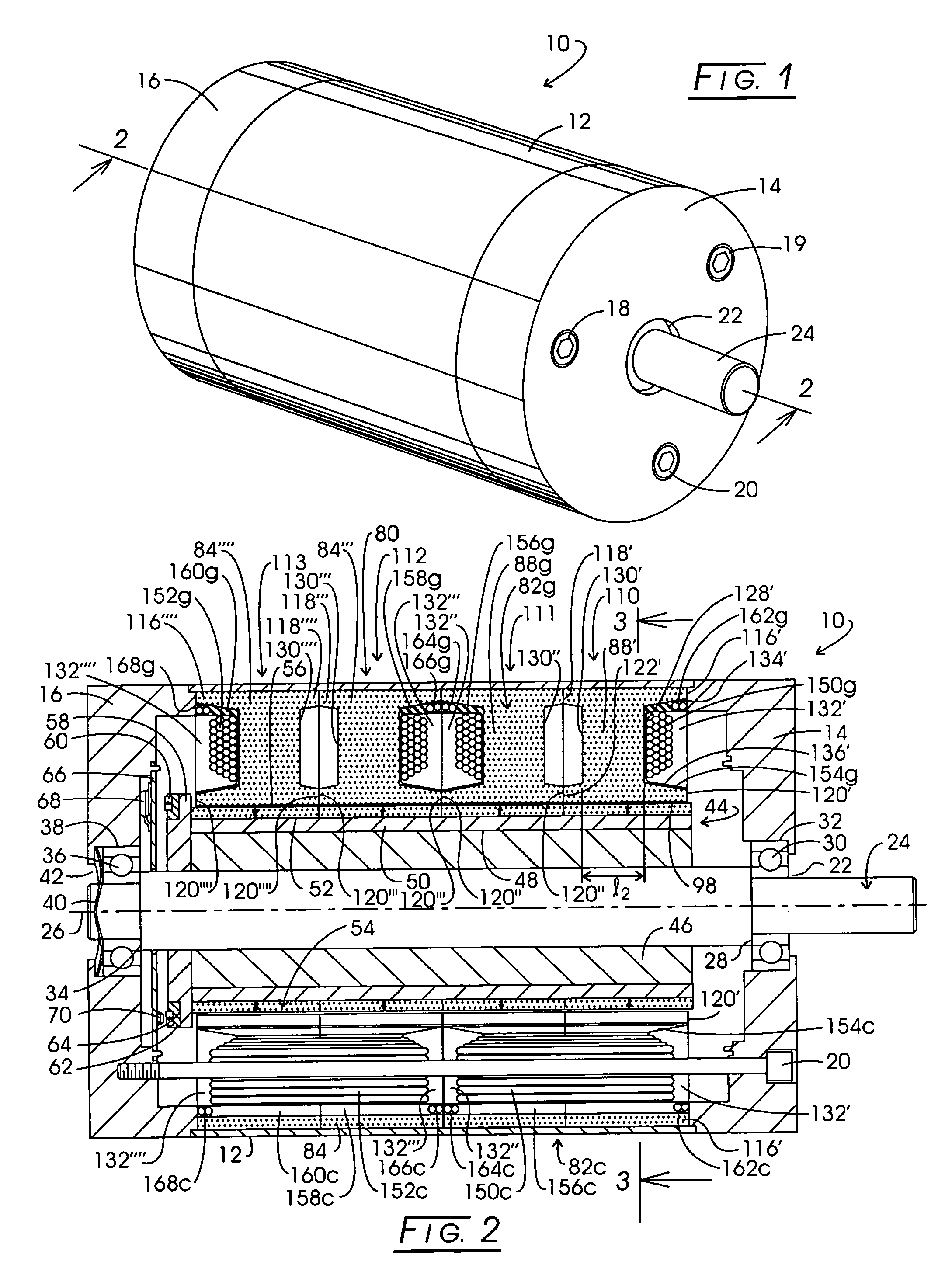
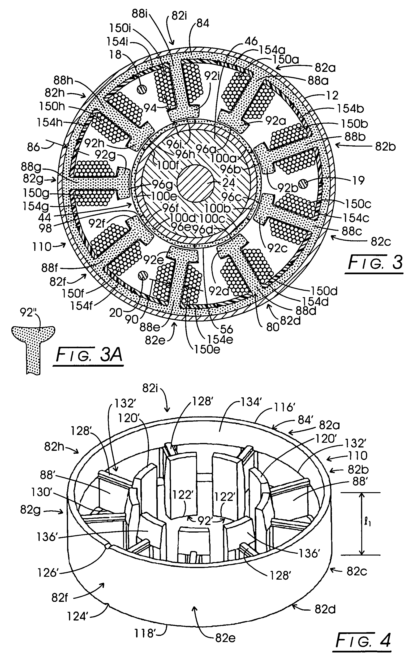
[0036]In the discourse to follow radially salient pole stator structures and the techniques of their formation and assembly are described in conjunction with d.c. PM motors having an architecture for deriving relatively higher power outputs, for example, about 250 watts and above. The structuring and techniques apply additionally to other forms of motors such as double salient pole motors and to electricity generators. Thus, the term “electrodynamic apparatus” is utilized with the meaning that it incorporates motors and generators employing the noted techniques of stator formation. In developing such electrodynamic devices utilizing magnetically soft composite pressed powder technology for stator construction the developer will establish a variety of dimensional parameters for electrical reasons establishing, for instance, appropriate material thicknesses to achieve flux transfer and avoidance of saturation. These electrical criteria are generated by calculation. When those requisit...


PUM

PropertyMeasurementUnit
poweraaaaaaaaaa
lengthaaaaaaaaaa
lengthsaaaaaaaaaa

Abstract

Electrodynamic apparatus such as a motor, generator or alternator is configured having a stator core assembly formed of pressure shaped processed ferromagnetic particles which are pressure molded in the form of stator modules. These generally identical stator modules are paired with or without intermediate modules to provide the stator core structure for receiving field winding components. In one embodiment, two sets of the paired stator modules are combined in tandem to enhance operational functions without substantial diametric increases in the overall apparatus.

Description

CROSS-REFERENCE TO RELATED APPLICATIONSSTATEMENT REGARDING FEDERALLY SPONSORED RESEARCH[0001]Not applicable.BACKGROUND OF THE INVENTION[0002]Investigators in the electric motor arts have been called upon to significantly expand motor technology from its somewhat static status of many decades. Improved motor performance particularly has been called for in such technical venues as computer design and secondary motorized systems carried by vehicles, for example, in the automotive and aircraft fields. With progress in these fields, classically designed electric motors, for example, utilizing brush-based commutation, have been found to be unacceptable or, at best, marginal performers.[0003]From the time of its early formation, the computer industry has employed brushless d.c. motors for its magnetic memory systems. The electric motors initially utilized for these drives were relatively expensive and incorporated a variety of refinements, for instance as necessitated with the introduction...

Claims


Application Information

Patent Timeline
Patent Type & Authority Patents(United States)
IPC IPC(8): H02K15/12H02K16/04H02K21/16
CPCH02K16/04H02K21/16Y10T29/49009
Inventor PETERSEN, CHRISTIAN C.
Owner PETERSEN TECH
Why Eureka
Try Eureka