Liquid-cooled electromotor

a technology of electric motors and electromotors, which is applied in the direction of piston pumps, magnetic circuit rotating parts, magnetic circuit shapes/forms/construction, etc., can solve the problems of increasing the outlay and production costs, increasing the losses of electric motors, and increasing the production costs

Inactive Publication Date: 2006-02-28
ELIN EBG MOTOREN
View PDF12 Cites 38 Cited by
  • Summary
  • Abstract
  • Description
  • Claims
  • Application Information

AI Technical Summary

Benefits of technology

[0048]The invention further provides for a method for cooling an electric motor having bearings and being coupled to a hydraulic pump, wherein the method comprises feeding a cooling liquid to a casing of the electric motor, moving the cooling liquid through at least one cavity of the casing, directing the cooling liquid to internal chambers surrounding bearings of the electric motor, providing a first sealing between the hydraulic pump and the electric motor, providing a second sealing at least between the one internal chamber and an interior of the electric motor, and allowing the cooling liquid to exist from the casing, wherein the cooling liquid moves between the internal chambers through the at least one cavity.

Problems solved by technology

On the one hand, it must, of course, be designed to be electrically insulated, and, on the other hand, it must ensure the unimpeded throughflow of the hydraulic fluid, thus obviously directly increasing the outlay and costs in production terms.
Moreover, the losses of the electric motor are, of course, increased due to an appreciably higher rotational resistance, since it has to run completely in the hydraulic fluid.

Method used


Image

  • Liquid-cooled electromotor
  • Liquid-cooled electromotor
  • Liquid-cooled electromotor

Examples


Embodiment Construction

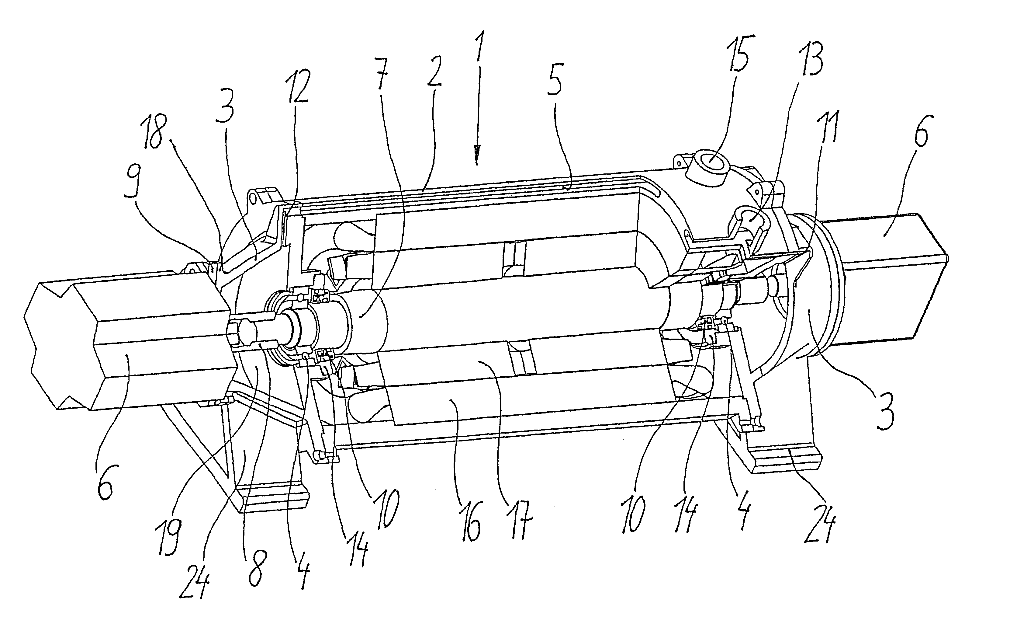
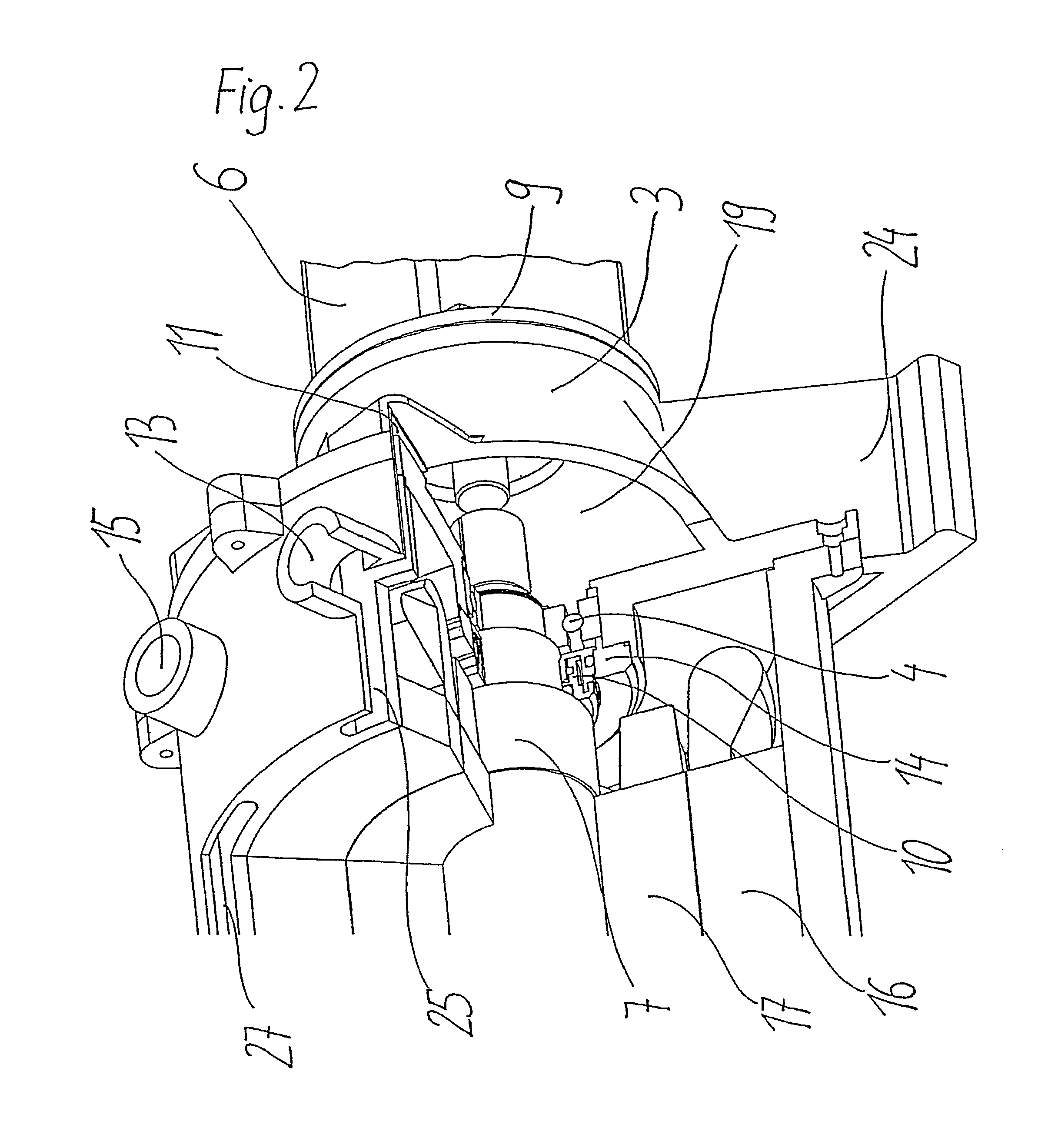
[0054]The invention is described below with reference to FIG. 1. The enlarged illustration in FIG. 2 serves for greater clarity.

[0055]The electric motor 1 with a stator 16, which is fastened to the inside of the motor housing 2, and with a rotor 17, which is fastened on the motor shaft 7, is located in a motor housing 2. Each side of the motor housing 2 has adjacent to it on the end face a bearing plate 3, in which a bearing 4 for the motor shaft 7 is held in each case. The bearings 4 are fixed in the bearing plates 3 in each case by way of a bearing holder 14. The bearing plates 3 are flush on the end face with a flange 18. Various types of hydraulic pumps 6 can be flanged on onto the electric motor 1 at these flanges 18 by way of different adapter rings 9. The hydraulic pumps 6 flanged on on both sides of the electric motor 1 are connected to the motor shaft 7 in each case via a coupling 8 and are therefore driven directly by the electric motor 1. In the present exemplary embodime...


PUM


Abstract

A liquid-cooled electric motor with a motor shaft, with two bearing plates which are mounted on the end faces of the motor housing and which carry on each side at least one bearing, the motor shaft being mounted rotatably in the bearings, and with at least one rotating hydraulic pump, the drive shaft of which is connected to the motor shaft by way of a coupling and which is driven by the electric motor. The casing of the motor housing receives a cooling liquid, has an at least partially hollow design and forms a casing cavity. At least one connecting duct for the supply of cooling liquid from the casing cavity to the bearings for cooling and lubrication of the bearings is provided in each of the bearing plates and in that said flanged-on hydraulic pump is sealed off in a liquid-tight manner with respect to the bearing plate interiors.

Description

CROSS-REFERENCE TO RELATED APPLICATIONS[0001]The present application is a National Stage Application of International Application No. PCT / EP01 / 10474, filed Sep. 11, 2001. Further, the present application claims priority under 35 U.S.C. § 119 of German Patent Application No. 100 45 424.0 filed on Sep. 14, 2000.BACKGROUND OF THE INVENTION[0002]1. Field of the Invention[0003]The present invention relates to a liquid-cooled electric motor, with a motor shaft, two bearing plates which are mounted on the end faces of the motor housing and which carry on each side at least one bearing. The motor shaft is mounted rotatably in said bearings, and the motor also includes at least one rotating hydraulic pump, for example an axial-piston, vane or gear pump, the drive shaft of which is connected to the motor shaft by way of a coupling and which is driven by the electric motor. The present invention also relates to a corresponding method.[0004]2. Discussion of Background Information[0005]U.S. Pat....

Claims


Application Information

Patent Timeline
Patent Type & Authority Patents(United States)
IPC IPC(8): H02K9/20F04B17/03F04B53/08F04C11/00F04C15/00H02K5/173H02K5/20H02K7/14H02K9/19
CPCF04B17/03F04B53/08F04C11/008F04C15/008H02K9/19H02K5/20F04C15/0096H02K5/1732H02K7/14H02K5/203
Inventor SCHULZ, RUDOLFFRICKH, MARKUSHORZ, EWALD
Owner ELIN EBG MOTOREN
Why Eureka
Try Eureka