Transmission line type noise filter with reduced heat generation even when large DC current flows therein

Active Publication Date: 2006-02-28
TOKIN CORP
View PDF13 Cites 7 Cited by
  • Summary
  • Abstract
  • Description
  • Claims
  • Application Information

AI Technical Summary

Benefits of technology

[0015]It is therefore an object of the present invention to provide a transmission line type noise filter with reduced heat generation even when a large DC current flows therein.
[0016]It is therefore another object of the present invention to provide the transmission line type noise filter that is excellent in noise removing characteristic over a wide band including a high frequency band and that has a small size and a simple structure.

Problems solved by technology

However, high-frequency noise currents generated in LSI chips or the like are spread from the LSI chips over wide ranges within circuit boards mounting the LSI chips by electric transmission including inductive coupling with signal wiring or ground wiring on the circuit boards, and further radiated as electromagnetic waves from the signal cables or the like around the circuit boards.
In a circuit comprising an analog circuit portion and a digital circuit portion, electromagnetic interference from the digital circuit portion to the analog circuit portion has become a serious problem.
Conventionally, however, it has been bothersome to select and design a plurality of noise filters that are used for removing electrical noise of a wide frequency band.
In addition, there has been a problem that the use of different kinds of noise filters makes the circuit high in cost, large in size, and heavy in weight.
However, the two-terminal lumped constant noise filters have difficulty in maintaining low impedances up to the high frequency band due to self-resonance phenomena of capacitors, and thus are inferior in performance of removing high-frequency band noise.
However, because the DC current to be supplied to the electrical load component passes in the transmission line type noise filter, heat is generated in the transmission line type noise filter.
Therefore, the transmission line type noise filter is serious in heat generation for use in an electrical circuit having a large DC current flowing therein, and the life of the transmission line type noise filter is therefore shortened.

Method used


Image

  • Transmission line type noise filter with reduced heat generation even when large DC current flows therein
  • Transmission line type noise filter with reduced heat generation even when large DC current flows therein
  • Transmission line type noise filter with reduced heat generation even when large DC current flows therein

Examples


Embodiment Construction

[0030]Now, transmission line type noise filters according to preferred embodiments of the present invention will be described hereinbelow with reference to the drawings.

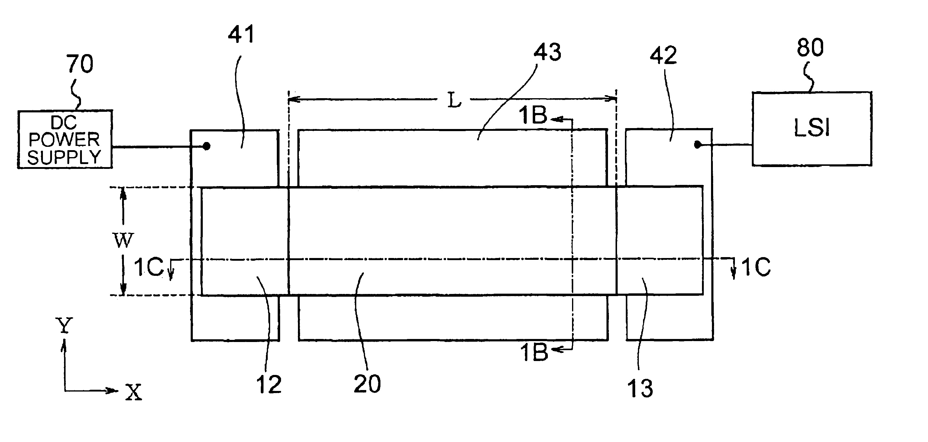
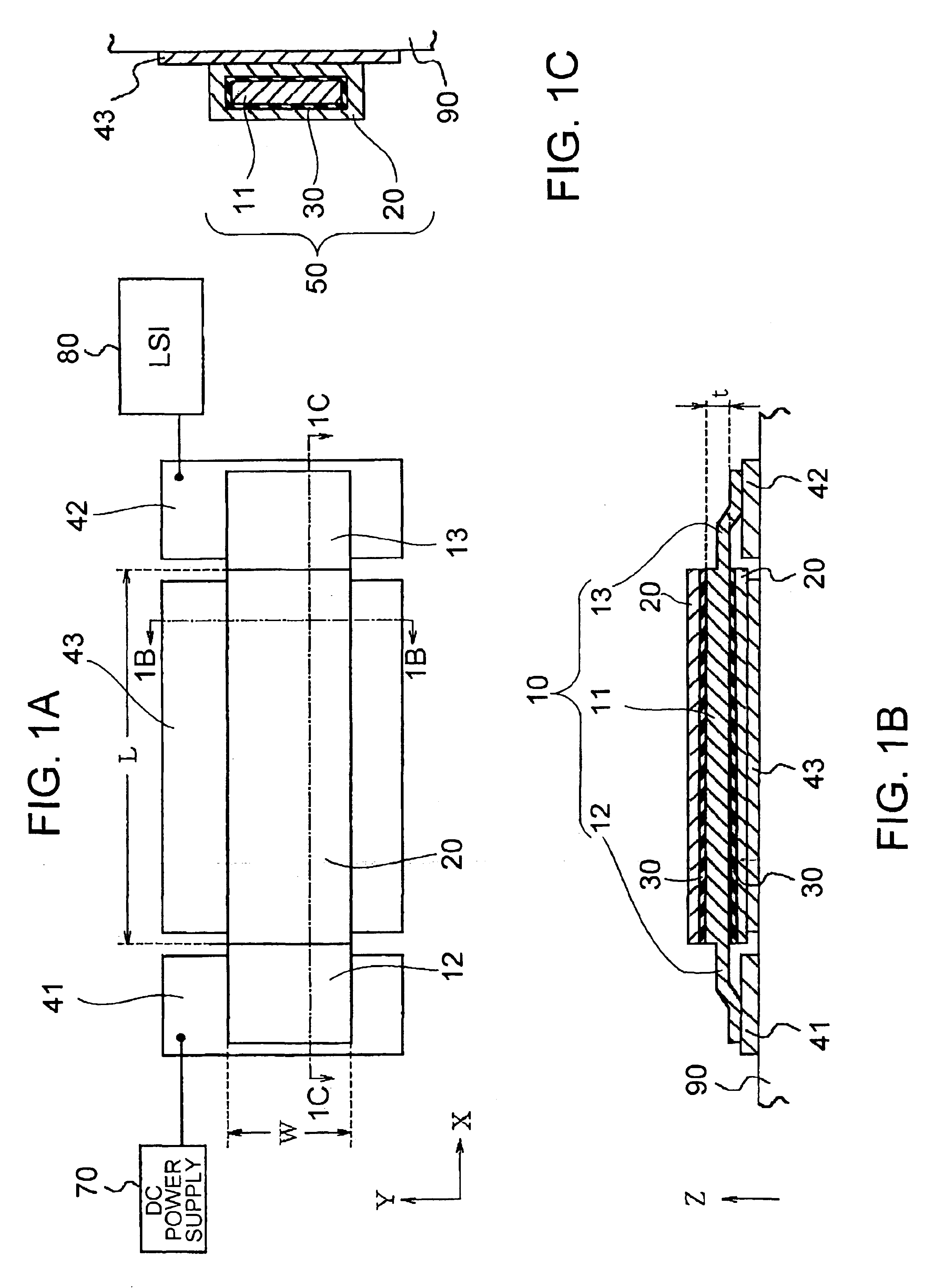
[0031]Referring to FIGS. 1A to 1C, a transmission line type noise filter according to an embodiment of the present invention is connectable between a direct current power supply (DC power supply) 70 and an LSI chip 80 as an electrical load component and can pass a coming direct current while can attenuate a coming alternating current.

[0032]The transmission line type noise filter comprises a first conductor 11, a dielectric layer 30, a second conductor 20, a first anode 12, and a second anode 13.

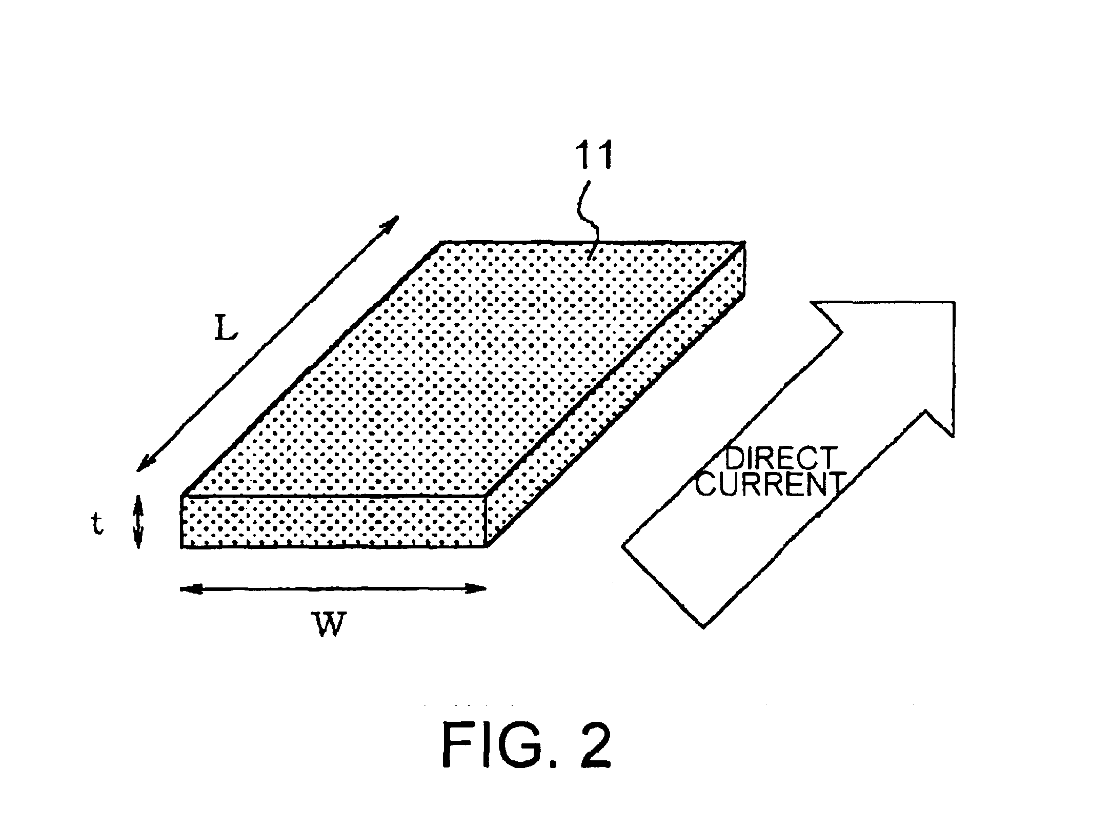
[0033]The first conductor 11 is plate-shaped and has a length L along a first direction X parallel to a transmission line, a width W along a second direction Y perpendicular to the first direction X, and a thickness t along a third direction Z perpendicular to the first and the second directions X, Y. The dielectric layer 30 i...


PUM


Abstract

A transmission line type noise filter, which is connectable between a direct current power supply and an electrical load component to pass a coming DC current while attenuating a coming AC current, includes a first conductor, a dielectric layer, a second conductor as a cathode, a first anode (12), and a second anode. The first and the second conductors and the dielectric layer serve as a capacitance forming portion. The thickness of the first conductor is selected to substantially restrict temperature elevation of the first conductor, which is caused by DC direct current flowing in the first conductor.

Description

[0001]This invention claims priority to prior Japanese patent application JP 2002-222925, the disclosure of which is incorporated herein by reference.BACKGROUND OF THE INVENTION[0002]The present invention relates to a noise filter that is mounted in an electronic device or electronic equipment for removing noise generated in the device or equipment.[0003]Digital technologies are important technologies supporting IT (Information Technology) industries. Recently, digital circuit technologies such as LSI (Large Scale Integration) have been used in not only computers and communication-related devices, but also household electric appliances and vehicle equipment.[0004]However, high-frequency noise currents generated in LSI chips or the like are spread from the LSI chips over wide ranges within circuit boards mounting the LSI chips by electric transmission including inductive coupling with signal wiring or ground wiring on the circuit boards, and further radiated as electromagnetic waves ...

Claims


Application Information

Patent Timeline
IPC IPC(8): H03H7/00H01P1/20H03H9/00H01P1/203
CPCH01P1/2007H03H9/00
Inventor ARAI, SATOSHIINOI, TAKAYUKISAIKI, YOSHIHIKOTOITA, SADAMU
Owner TOKIN CORP
Why Eureka
Try Eureka