System for and method of exchanging server data in packet unit

a server and packet unit technology, applied in the field of server systems, can solve problems such as unavailability of message transmission to terminal equipment, and achieve the effect of efficient server data processing

Inactive Publication Date: 2006-02-28
HITACHI LTD
View PDF38 Cites 4 Cited by
  • Summary
  • Abstract
  • Description
  • Claims
  • Application Information

AI Technical Summary

Benefits of technology

[0021]According to the present invention, as described above, a server system can be utilized by making use of—extensions of an exchanger. Therefore, a user can freely travel over each terminal equipment which makes use of a server. Since both a telephone and the server system can be utilized through the same network, it is unnecessary to doubly lay cables for their purposes. By making use of the identical logical channel corresponding to each server device, a plurality of pieces of terminal equipment can simultaneously set up or establish a packet link and accept a plurality of use requests to the identical server. Therefore, any user is no longe±− placed on a process waiting state because server' use requests do not compete with each other. When the user attempts to use the server, a server name to be used is assembled into data, and thus-processed data is delivered to the system. In addition, the system examines a physical address of the server, fol

Problems solved by technology

If it is judged that the user cannot utilize the system on the other han

Method used


Image

  • System for and method of exchanging server data in packet unit
  • System for and method of exchanging server data in packet unit
  • System for and method of exchanging server data in packet unit

Examples


first embodiment

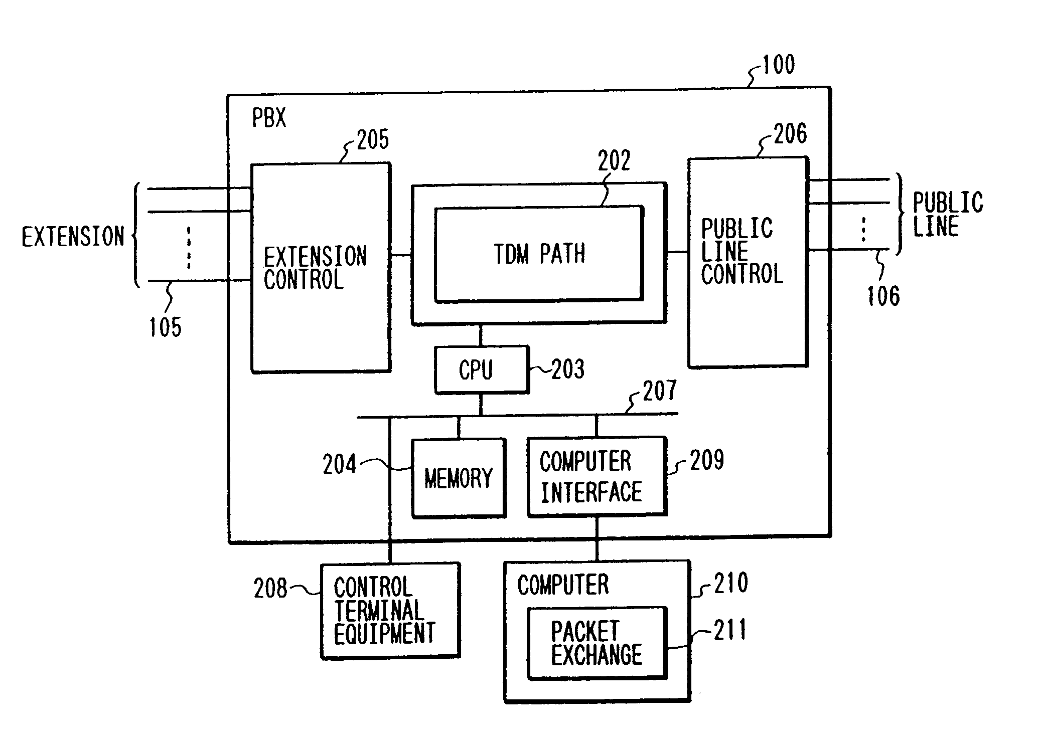
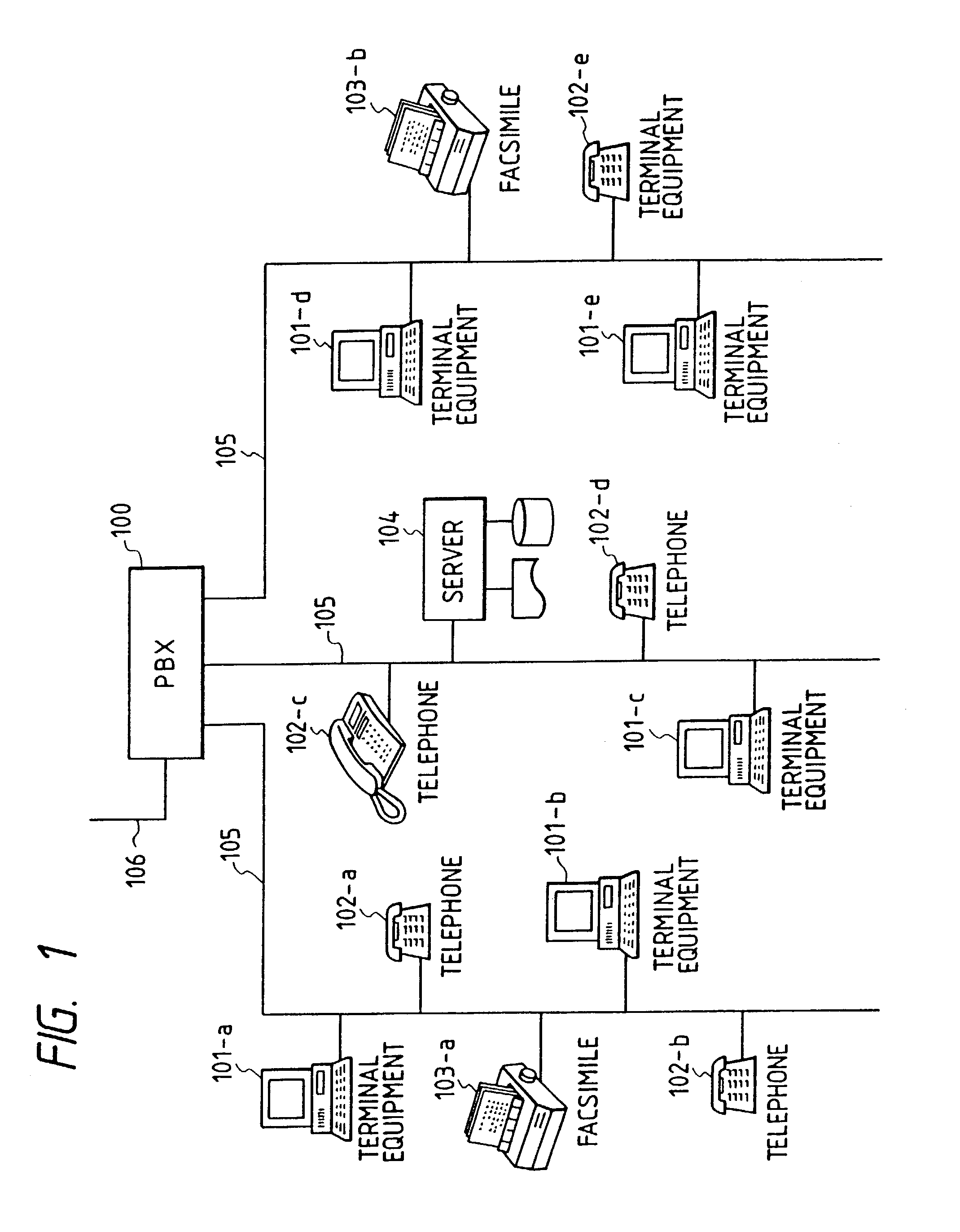
[0057]Preferred embodiments of the present invention will hereinafter be described with the accompanying drawings. FIG. 1 shows a PBX server system to which a system for exchanging server data in a packet unit, i.e., a sever data packet exchange system of the present invention is applied. The PBX server system basically comprises a digital public branch exchange (hereinafter referred to as a “PBX”) 100, a plurality of pieces of terminal equipment 101, and a server 104. The terminal equipment 101 and the server 104 can be connected to extensions 105 of the PBX through physical interfaces identical to those of devices such as telephones 102, facsimiles 103, the devices being used for a public telephone communication line. As has been provided in the advice 1.441 (ISDN user / network interface) of CCITT, each extension 105 of the PBX 100 is used to send a control signal transmitted and received between the PBX 100 and each terminal equipment 101 for the purpose of terminal connection an...

second embodiment

[0090]A description will now be made of a PBX server system according to the present invention with reference to the accompanying drawings.

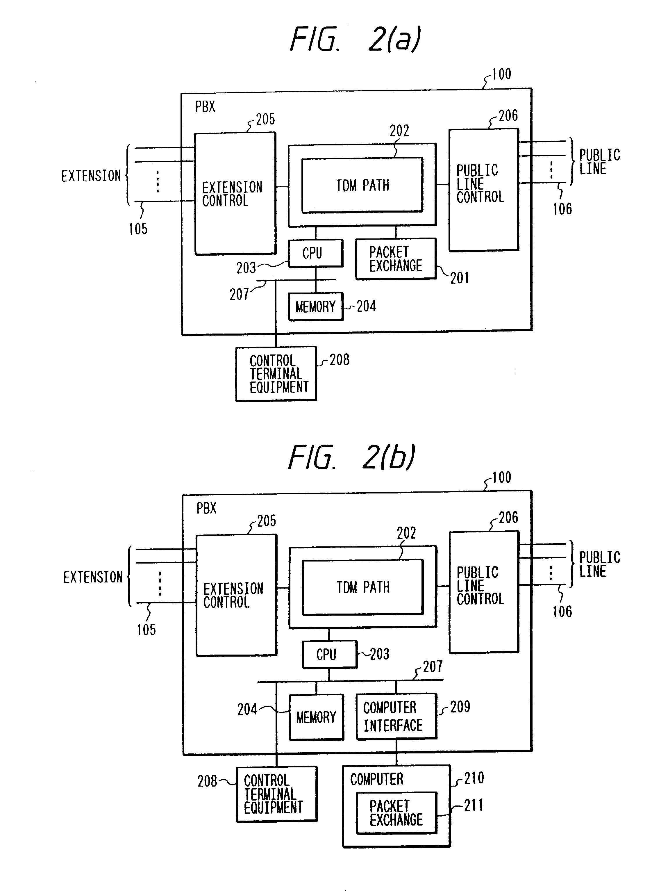
[0091]FIG. 29 shows a PBX server system according to the second embodiment of the present invention. The PBX server system comprises a PBX 2900, a server 2901 connected directly to the PBX 2900, telephones 102 electrically connected to extensions 105, and a plurality of pieces of terminal equipment 101. The present PBX server system differs from the PBX server system shown in FIG. 1 in that the server 2901 is directly connected to the PBX 2900.

[0092]FIG. 30 is a diagram schematically showing the structure of the inside of the PBX 2900. FIG. 30(a) shows the structure of the PBX in which a packet exchange 3001 for exchanging packet data between terminal equipment and each server is directly connected to a time-division multiplex (TDM) path 3202 in the PBX 2900. Also connected to the TDM path 3202 are a CPU 3003 for controlling the entire operation ...


PUM


Abstract

A packet switch apparatus including a plurality of connecting points, each being coupled to one of a plurality of data processing units, and apparatus for receiving a first packet including identification information of a first data processing unit via a first connecting point. The invention further includes a storage for storing correspondence between the first data processing unit and the first connecting point based on the identification information. Apparatus, responsive to reception of a second packet from a second data processing unit to be transmitted to the first data processing unit, transmits the second packet to the first data processing unit via the first connecting point based on the correspondence stored in the storage.

Description

[0001]The present application is a continuation of application Ser. No. 09 / 161,731, filed Sep. 29, 1998, now U.S. Pat. No. 6,621,816; which is a continuation of application Ser. No. 08 / 653,276, filed May 24, 1996, now U.S. Pat. No. 6,141,338; which is a continuation of application Ser. No. 07 / 798,965, filed Nov. 27, 1991, now U.S. Pat. No. 5,537,401, the contents of which are incorporated herein by reference.BACKGROUND OF THE INVENTION[0002]The present invention relates to a server system of a type wherein the sharing of resources can be carried out using extensions of a private branch exchange (PBX), and more specifically to a system for and a method of exchanging server data in a packet unit, of a type wherein a plurality of users can simultaneously utilize the same resource.[0003]As one of conventional arts, there is known one disclosed in Japanese Patent Application Laid-Open No. 1-109847. According to the disclosure, peripheral devices such as a printer, hard disc are electrica...

Claims


Application Information

Patent Timeline
IPC IPC(8): H04L12/66H04Q3/58H04L12/28H04L12/70H04L29/06H04M9/02
CPCH04L12/2854H04M7/1205H04M9/02H04Q3/625H04M3/42314H04Q2213/13093H04L67/42H04Q2213/13103H04Q2213/13106H04Q2213/1322H04Q2213/13299H04Q2213/13339H04Q2213/13389H04Q2213/13096H04L67/01
Inventor TADAMURA, KATSUMIYASUE, TOSHIKAZUKAGEYAMA, SEIJIOURA, TETSUO
Owner HITACHI LTD
Why Eureka
Try Eureka