Engine delay compensation

Inactive Publication Date: 2006-02-28
DETROIT DIESEL CORP
View PDF8 Cites 35 Cited by
  • Summary
  • Abstract
  • Description
  • Claims
  • Application Information

AI Technical Summary

Benefits of technology

[0012]In another embodiment of the present invention, the control logic generates the disturbance estimate based on an error signal found as a difference between the desired input and a combination of the controlled output and the engine model output.
[0013]A method for controlling an engine with transport delay is also provided. A control signal, generated for the engine control input, is determined for controlling the engine as if the engine was without the delay. The control signal is based on an error signal. The disturbance is estimated. A compensating signal is generated based on a model for the engine and on the estimated disturbance. The error signal is generated as a difference between a desired input and a sum of the controlled output and the compensation signal.
[0014]In an embodiment of the present invention, generating a compensating signal includes generating a disturbance corrected signal by subtracting the estimated disturbance from the control signal and generating the compensating signal by passing the disturbance corrected signal through an engine model for the e

Problems solved by technology

The engine has a control input and a contro

Method used


Image

  • Engine delay compensation
  • Engine delay compensation
  • Engine delay compensation

Examples


Embodiment Construction

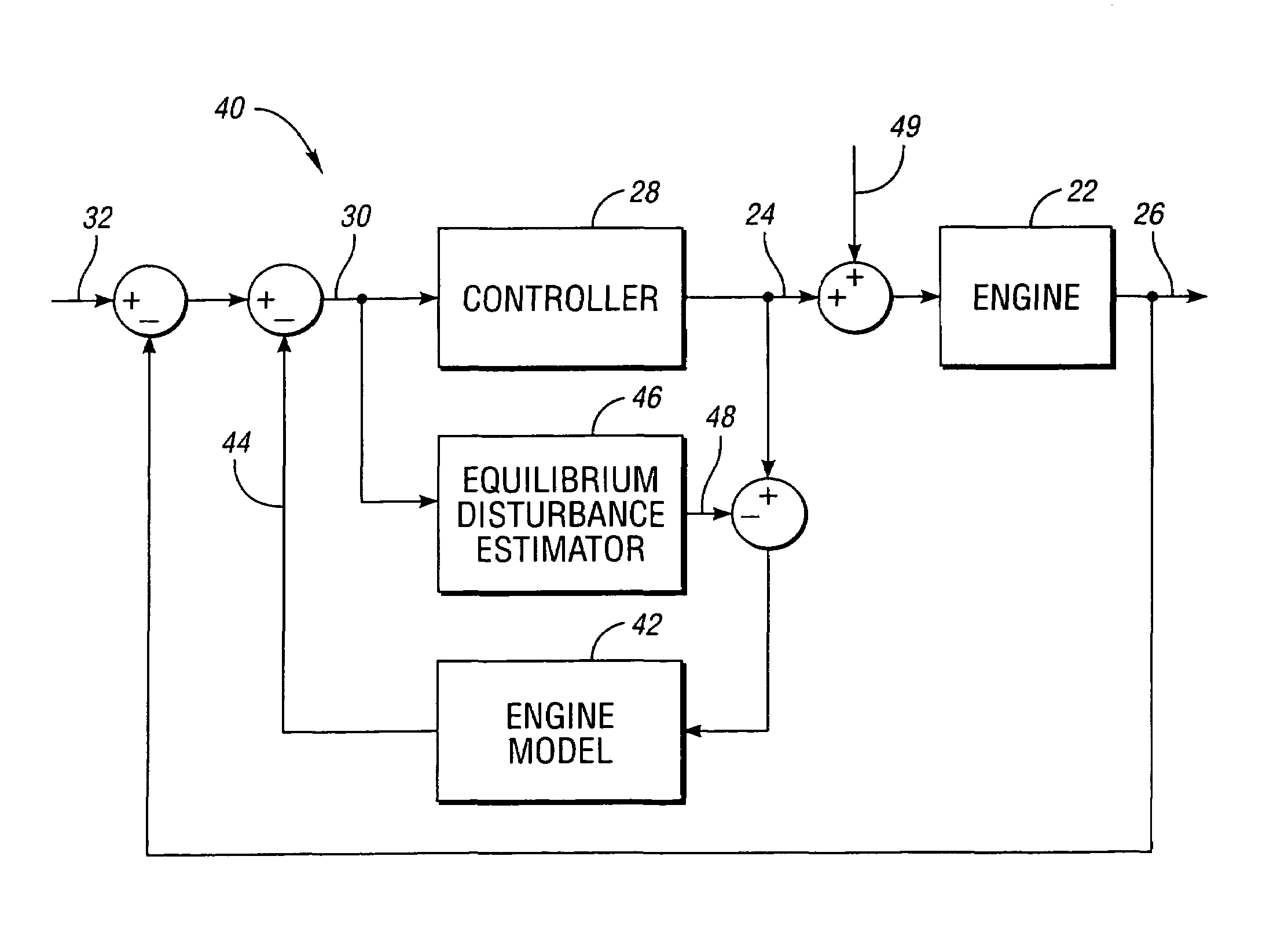
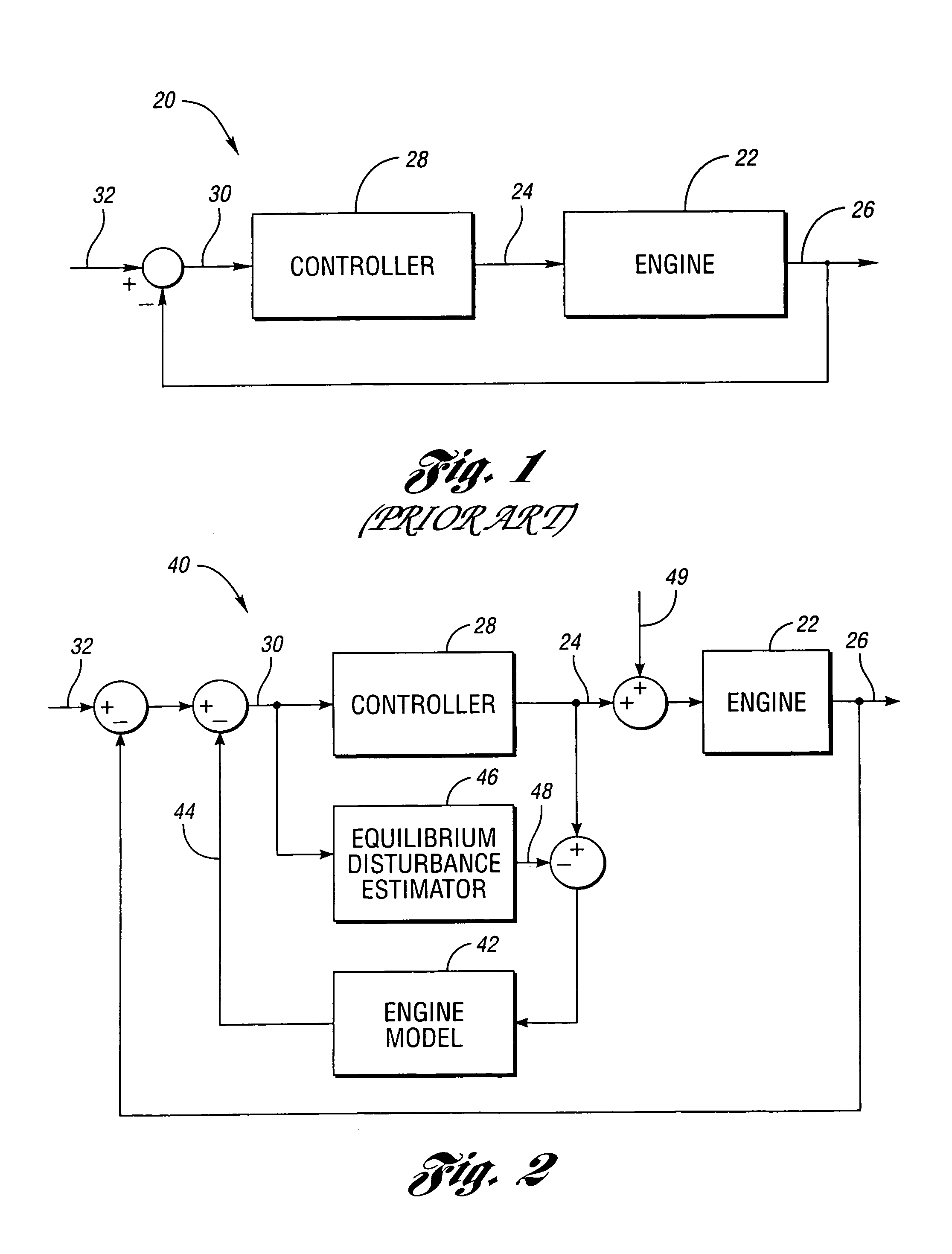
[0032]Referring to FIG. 1, a block diagram of a prior art engine control system is shown. An engine control system, shown generally by 20, includes one or more engine parameters to be controlled, represented by block 22. Engine parameters 22 have at least one control input 24 for modifying parameters 22 resulting in one or more controlled outputs 26. Without loss of generality, the remainder of this discussion will assume a single engine parameter 22 generating a single controlled output 26 based on a single control input 24. It will be recognized by one of ordinary skill in the art that the present invention is equally applicable to multiple parameters 22 with multiple control inputs 24 and controlled outputs 26.

[0033]Controller 28 generates control input 24 based on error signal 30. Error signal 30 is calculated as the difference between desired input 32 and controlled output 26. Closed-loop controller 28 is designed to control how controlled output 26 tracks desired input 32.

[003...


PUM


Abstract

An engine with inertial integration and delay is controlled through the use of a disturbance estimator. Control logic includes a feed-forward control path driving a control input with a control signal. The feed-forward control path is designed to provide closed-loop control of the controlled parameter without the presence of transport delay. The disturbance estimator generates an estimate of the engine disturbance. A Smith predictor generates a compensation signal for the feed-forward control path based on the control signal and the engine disturbance estimate.

Description

TECHNICAL FIELD[0001]The present invention relates to controlling internal combustion engines with inherent transport delay.BACKGROUND ART[0002]Internal combustion engines may have many parameters which must or may be controlled, including spark timing, fuel delivery, air intake, exhaust removal, emissions control, engine speed and torque, accessory control, and the like. Typically, the rotating mass of an engine has substantial inertia which inhibits immediate attempts to change engine parameters. This inertia is represented by integration when modeling the engine parameters.[0003]The control problem is complicated by the presence of delay between when an engine parameter changes and when the corresponding change in a controlling signal occurs. Such delay may be caused by the response time of a sensor detecting the engine parameter, by computational time required to calculate the control signal, and by the response time of an actuator designed to affect the engine parameter. For ex...

Claims


Application Information

Patent Timeline
IPC IPC(8): F02D41/14
CPCF02D41/1401F02D41/1403F02D2041/141F02D2041/1431F02D2041/1433G05B11/42G05B13/048
Inventor MAY, ANDREW
Owner DETROIT DIESEL CORP
Why Eureka
Try Eureka