
Method and mechanism for RTL power optimization

a technology of power optimization and power optimization, applied in the direction of cad circuit design, program control, instruments, etc., can solve the problems of significant waste, substantial amount of power, and difficulty in the design process, and achieve the effect of saving a substantial amount of power and high potential for saving power

Active Publication Date: 2006-02-28
CADENCE DESIGN SYST INC
View PDF35 Cites 17 Cited by
  • Summary
  • Abstract
  • Description
  • Claims
  • Application Information

AI Technical Summary

Benefits of technology

The patent text describes a method and mechanism for optimizing the power consumption of micro-electronic circuits. The method involves identifying candidates for applying power saving techniques and modifications, and marking them within the circuit without modifying their data and control paths. Each technique and modification is then evaluated to determine if it saves power and satisfies the timing requirement of the circuit. Additionally, each technique and modification is reduced to determine if it improves the circuit's timing. This approach helps to avoid unnecessary power consumption and timing issues during the design process, resulting in faster and more efficient circuit designs.

Problems solved by technology

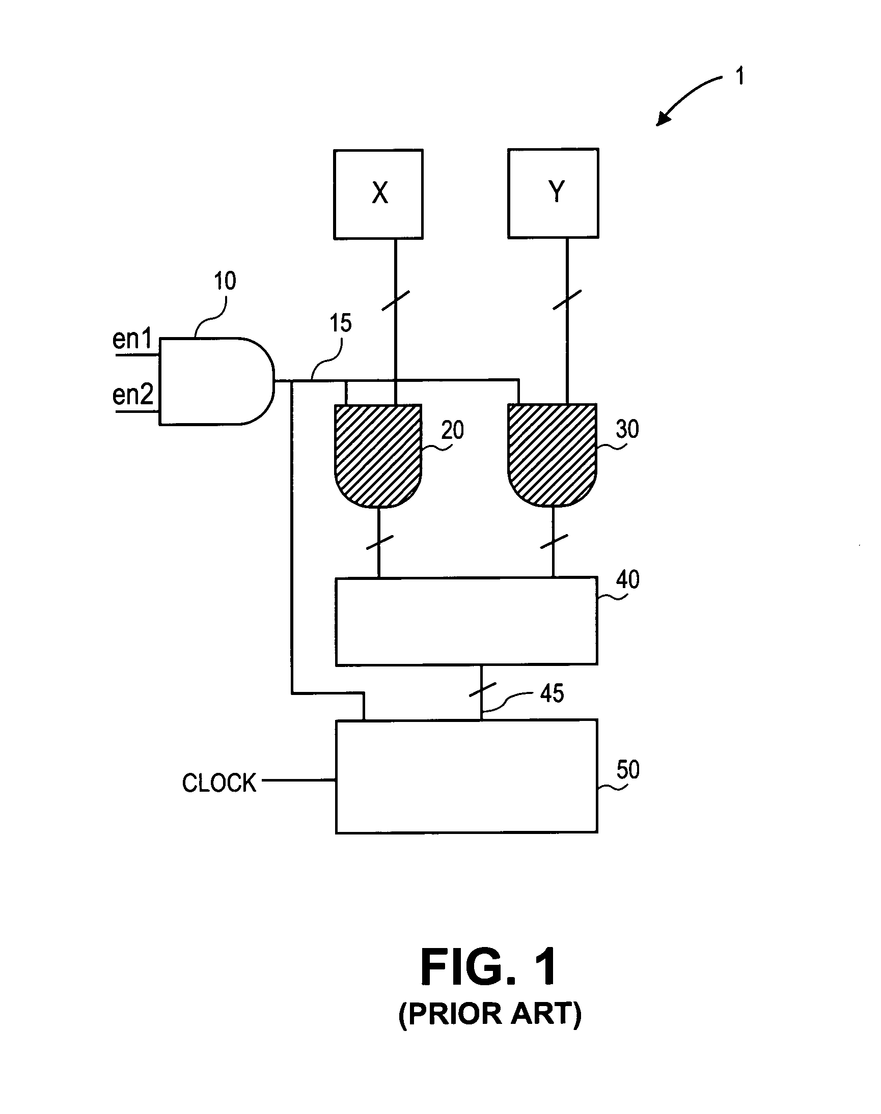
Particularly, power optimization techniques and / or modifications applied at the register-transfer level (RTL)—where the system is conceptualized in terms of registers and data transfers—may save a substantial amount of power.
This waste may be significant because the multiplier 40 typically consumes a substantial amount of power.
However, the tools generally require that the techniques and modifications be applied during the synthesis of the micro-electronic circuits, when the circuit has yet to be optimized and simulated.
Thus, power consumption and timing—another important optimization metric—have to be estimated, which may cause some difficulty in the design process.
Generally, faster performing circuits consume more power.
Thus, in some instances, adding power saving techniques and / or modifications may cause the circuit to perform slower.
If, after timing and logic optimization tools are applied, the timing requirement for design is violated, then either the tools have to undo the sleep-mode transformations to improve the timing, or in the worst case, the developer may have to manually fix the timing problems.
But, if the timing and logic optimization tools are applied after the power saving techniques are applied, undoing the power saving techniques and / or modifications may not be a simple task.
Thus, if the timing optimization tools operate after the power saving techniques and / or modifications are applied, then the optimization tools may optimize the wrong critical paths, i.e., critical paths created by the power saving techniques and / or modifications.
When the timing optimization tools compensate for these wrong critical paths, the circuit may end up increasing the power consumption.
Further, undoing the technique and / or modification after optimization would be difficult in such a situation because the compensation done by the timing optimization tools would also have to be undone.
A lot of time and effort would be wasted during the design and synthesis process.

Method used


Image

  • Method and mechanism for RTL power optimization
  • Method and mechanism for RTL power optimization
  • Method and mechanism for RTL power optimization

Examples


Embodiment Construction

[0018]The present invention is disclosed in a number of embodiments as methods and mechanisms for optimizing the power consumption of a micro-electronic circuit. Some of the embodiments described use sleep-mode transformation as the power saving technique and / or modification. However, the principles presented here are applicable to any power saving technique and / or modification using any circuit design program, and thus the scope of the invention is not to be limited to the exact embodiments shown herein.

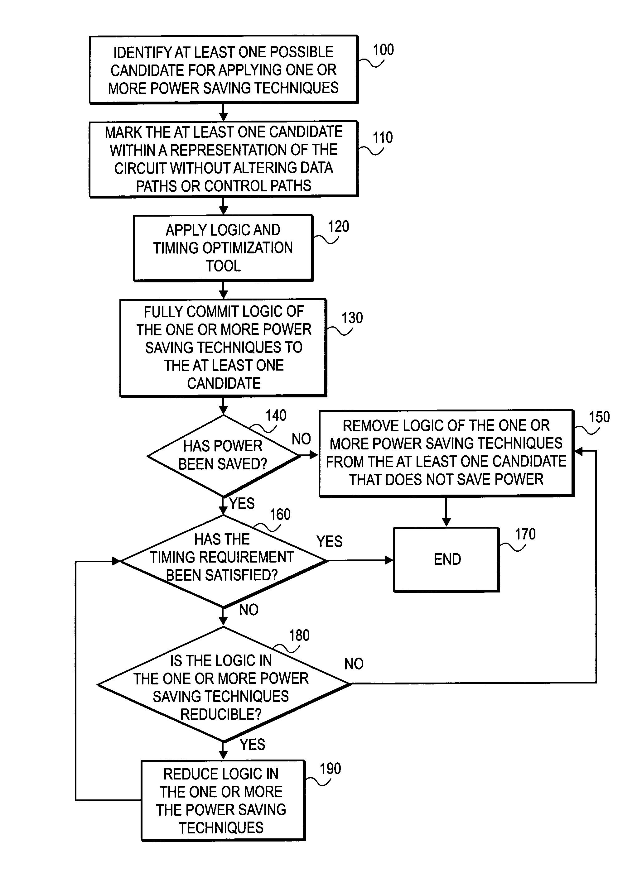
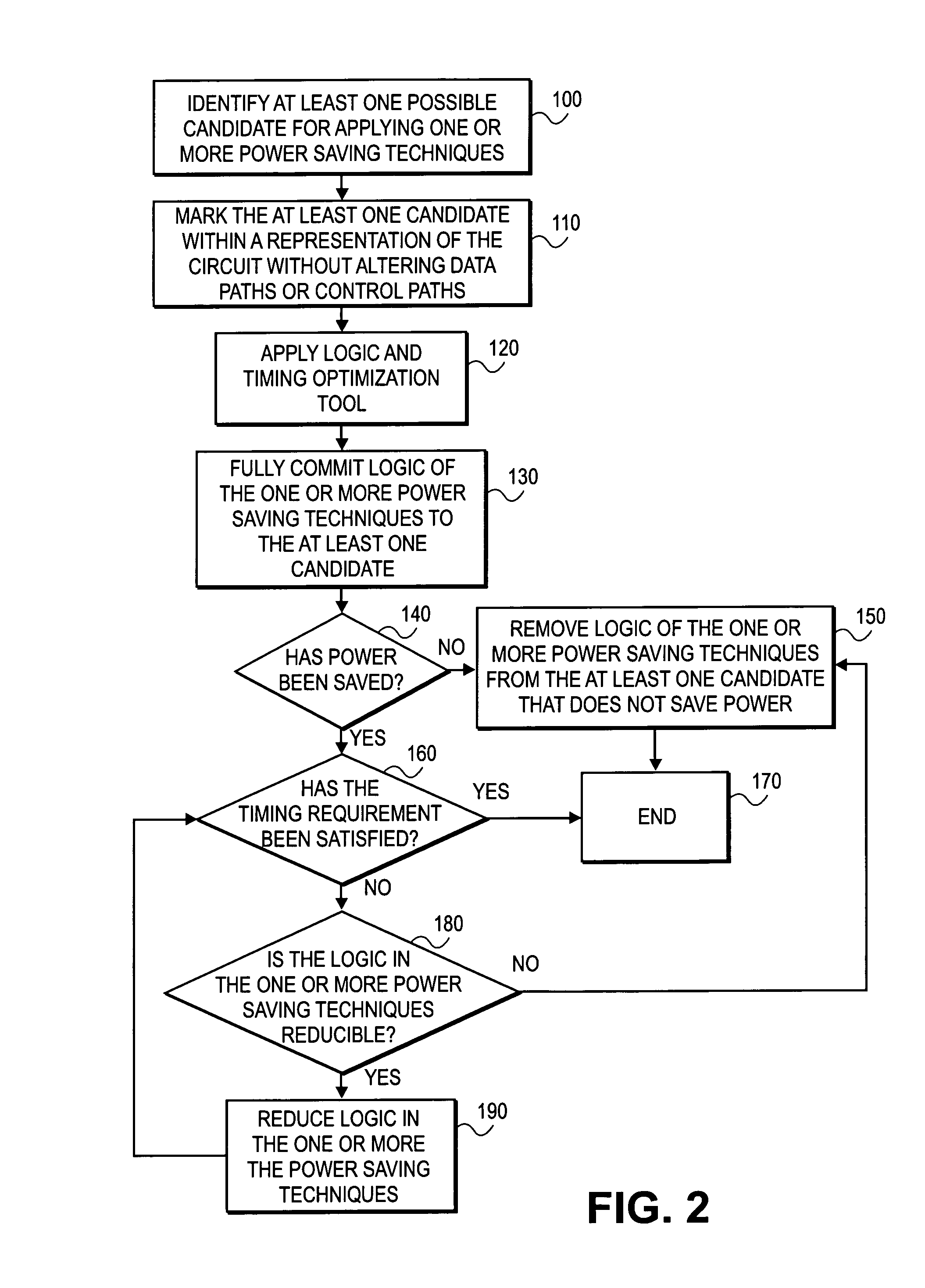
[0019]One approach to effectively apply power saving techniques and / or modifications to a micro-electronic circuit is illustrated in FIG. 2 as a method in accordance with an embodiment of the present invention. At the first step, one or more candidates are identified within the circuit to apply one or more power saving techniques and / or modifications (action block 100). This is preferably achieved during circuit synthesis at the RTL, which may be referred to as the RTL exploration p...


PUM


Abstract

The present invention provides a method and mechanism for optimizing the power consumption of a micro-electronic circuit. According to an embodiment, when optimizing the power consumption of a micro-electronic circuit, one or more candidates for applying one or more optimization techniques may be identified. Then, the one or more candidates may be marked with the one or more optimization techniques within the micro-electronic circuit without altering the data and / or control paths of the circuit. Then, after timing and logic optimization, each power saving technique applied to the one or more candidates may be evaluated to determine whether the technique saves power and / or satisfies the timing requirement of the circuit. Further, each power saving technique applied to the one or more candidates may be evaluated to determine whether the technique is reducible, and if so, then the technique may be reduced to determine whether such reduction improves the circuit's timing.

Description

BACKGROUND AND SUMMARY[0001]Power consumption has become an important optimization metric in the design of micro-electronic circuits. Optimizing the power consumption may be achieved at various abstract levels of design, from algorithmic and system levels down to layout and circuit levels. Typically, power optimization techniques applied at the higher abstract levels have a higher potential for saving power. Particularly, power optimization techniques and / or modifications applied at the register-transfer level (RTL)—where the system is conceptualized in terms of registers and data transfers—may save a substantial amount of power.[0002]For example, turning to FIG. 1, a circuit 1 having a register bank 50, coupled to a clock signal, that takes the result 45 of a multiplier 40 as its only input is shown at the RTL. The multiplier 40 has two inputs, x and y. The inputs and signals are digital and thus, will have either ON or OFF (1 or 0) values, or a combination thereof. In this circuit...

Claims


Application Information

Patent Timeline
Patent Type & Authority Patents(United States)
IPC IPC(8): G06F17/50
CPCG06F17/5045G06F2217/78G06F30/30G06F2119/06
Inventor WANG, QIROY, SUMIT
Owner CADENCE DESIGN SYST INC
Learn More