Gas turbine fuel system staging valves

a technology of gas turbine fuel system and staging valve, which is applied in the direction of combustion control, machines/engines, lighting and heating apparatus, etc., can solve the problems of negative effect on both performance and longevity

Active Publication Date: 2006-03-07
PARKER INTANGIBLES LLC
View PDF12 Cites 27 Cited by
  • Summary
  • Abstract
  • Description
  • Claims
  • Application Information

AI Technical Summary

Benefits of technology

[0008]The position of the normally-closed staging valve assembly is controlled by the pressure difference between the nozzle fuel supply circuit and a separately supplied signal circuit. As long as the desired pressure differential is maintained, fuel flow may be modulated without affecting the position of the valve assembly. During engine operation, the closed valve assembly, and particularly the main valve can be exposed to a wide range of fuel supply pressures. The valve seal and seat features of the present invention are configured to prevent fuel leakage into the downstream nozzle circuit under these conditions. This “No Leak” feature eliminates a fuel source that can contribute to combustor emissions and nozzle coking. Furthermore, this “No Leak” feature also prevents drainage of upstream fuel into the combustor at engine shutdown.

Problems solved by technology

A plurality of dynamic seals is required and moving parts of the valve are located downstream of the valve seat, all of which can have a negative effect upon both performance and longevity.

Method used


Image

  • Gas turbine fuel system staging valves
  • Gas turbine fuel system staging valves
  • Gas turbine fuel system staging valves

Examples


Embodiment Construction

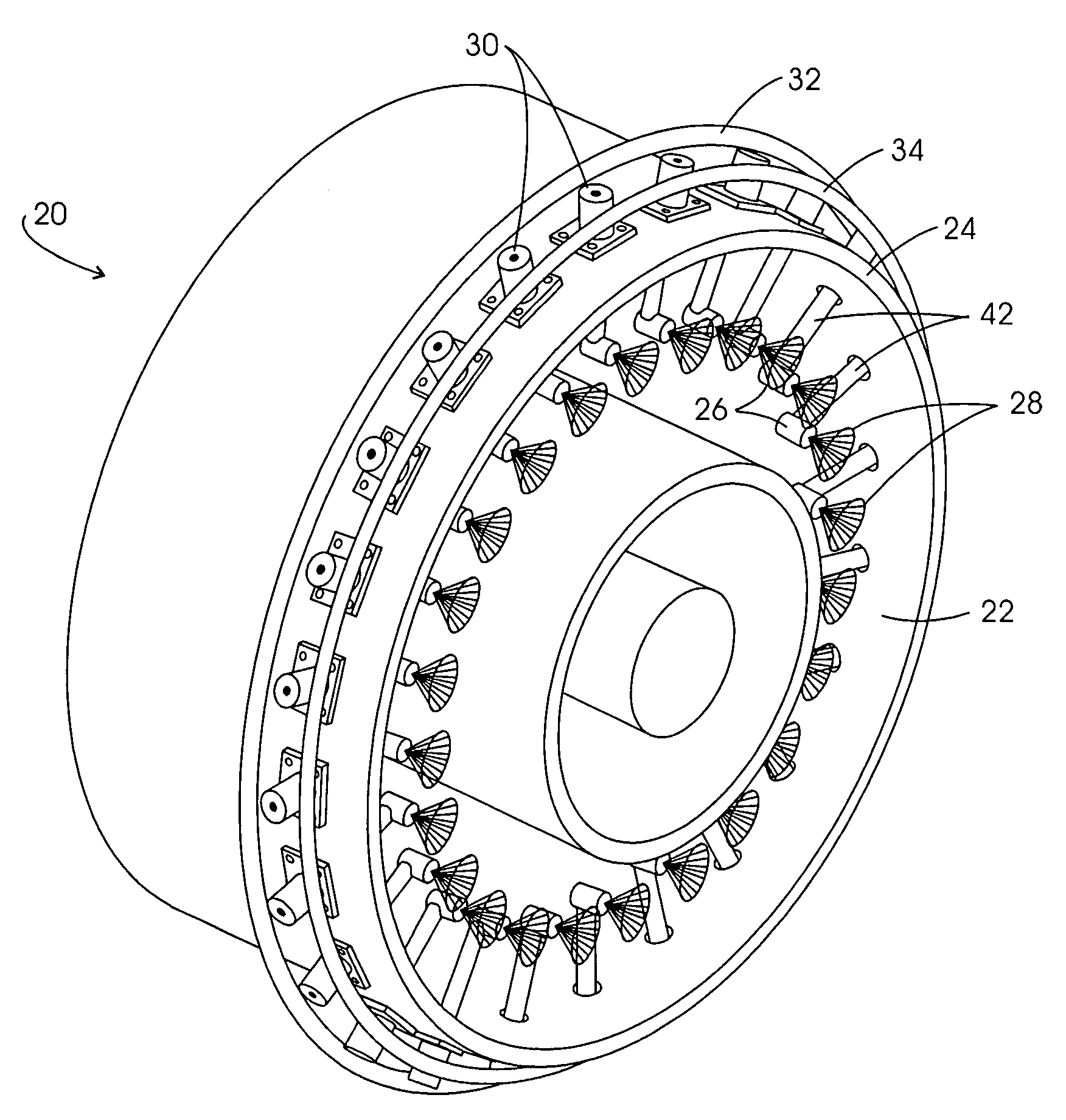
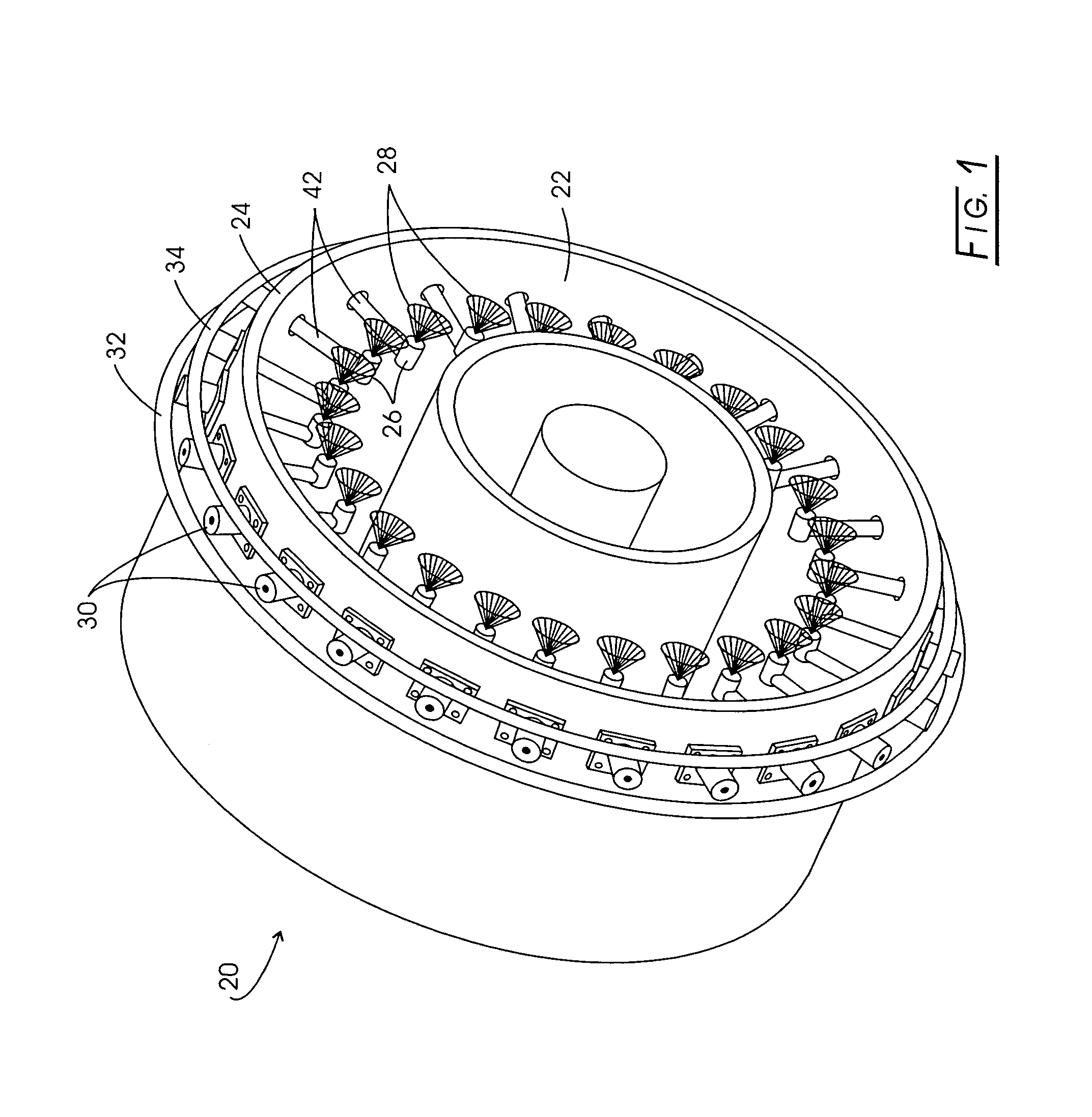
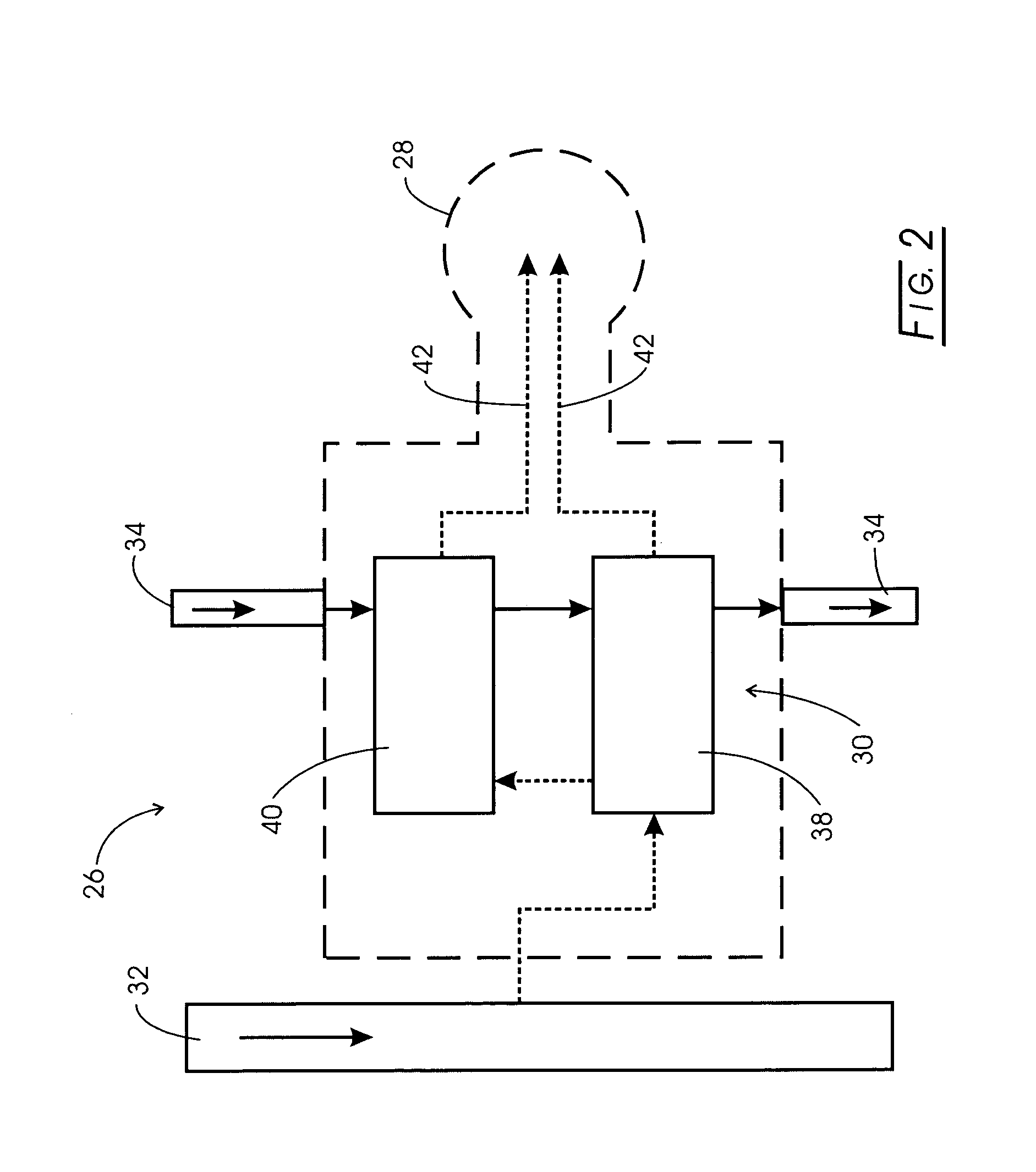
[0041]Referring now to the several drawings, and initially to FIG. 1, there is shown a schematic and greatly simplified portion of a gas turbine engine, generally indicated at 20. Mounted on an upstream, outer wall portion 24 of a combustion chamber 22 are a plurality fuel injector assemblies, for example as indicated generally at 26. Each fuel injector assembly 26 includes a nozzle tip 28 and a fuel staging valve assembly 30, which is constructed according to the present invention. The plurality of preferentially circumferentially-spaced fuel injector assemblies 26, each including a fuel staging valve assembly 30, are connected via circumferential main fuel manifold 32 and signal fuel manifold 34. Combustion chamber 22 is a typical combustion chamber for aircraft engine applications, known to those skilled in the art, and will thus not be discussed further, for the sake of brevity. Fuel injector assemblies 26 atomize and direct fuel into combustion chamber 22 for ignition. A compre...


PUM


Abstract

In a fuel injector circuit for a gas turbine engine, a fuel staging valve assembly for distributing fuel into multiple zones in the combustor, the staging valve assembly, including a pilot valve operatively interconnected with at least one main valve, having high pressure and no leak capabilities, which are used to open, close and modulate the mass flow rate volume of fuel within the fuel injection circuit, with the position of the normally-closed valve being controlled by the pressure difference between the nozzle fuel supply circuit and a separately supplied signal circuit. As long as the desired pressure differential is maintained, fuel flow may be modulated without affecting the position of the valve, with the valve seats and valve seals being so configured as to prevent fuel leakage into the downstream nozzle circuit under these conditions.

Description

CROSS-REFERENCE TO RELATED CASES[0001]The present application claims the benefit of the filing date of U.S. Provisional Application Ser. No. 60 / 462,797 filed Apr. 11, 2003, the disclosure of which is incorporated herein by reference.FIELD OF THE INVENTION[0002]The present invention generally relates to gas turbine engines, and more particularly, to fuel injectors for supplying fuel to nozzles in such engine combustion chambers wherein, for each nozzle, a fuel staging valve assembly, including an operatively interconnected pilot valve and at least one main valve, distribute fuel in a predetermined manner.BACKGROUND OF THE INVENTION[0003]Fuel injector assemblies are useful for applications such as gas turbine combustion engines for directing pressurized fuel from a manifold to one or more combustion chambers. Such assemblies also function to prepare the fuel for mixing with air prior to combustion. Each injector assembly typically has an inlet fitting connected the manifold, a tubular...

Claims


Application Information

Patent Timeline
Patent Type & Authority Patents(United States)
IPC IPC(8): F02C7/228F02C7/232F23N1/00
CPCF23N1/002F23N2035/18Y02T50/677F23N2037/02F23N2041/20F23N2035/24F23N2235/18F23N2235/24F23N2237/02F23N2241/20Y02T50/60
Inventor MAINS, ROBERT THANELEHTINEN, JEFFREY R.
Owner PARKER INTANGIBLES LLC
Why Eureka
Try Eureka