AC type flowmeter and method of mapping flow rate data for the same

a flowmeter and flow rate technology, applied in the direction of fluid speed measurement, speed/acceleration/shock measurement, instruments, etc., can solve the problems of limited measurement range of calorimetric type sensors, difficult to find sensors simultaneously satisfying the above requirements, etc., to achieve simplified structure, wide measurement range, and high measurement accuracy

Active Publication Date: 2006-03-07
SEOUL NAT UNIV R&DB FOUND
View PDF2 Cites 40 Cited by
  • Summary
  • Abstract
  • Description
  • Claims
  • Application Information

AI Technical Summary

Benefits of technology

[0011]Accordingly, the present invention has been made keeping in mind the above problems occurring in the prior art, and an object of the present invention is to provide an AC type flowmeter, which has a wide measurement range and high measurement accuracy while having a simplified structure, and a method of mapping flow rate data for the flowmeter.

Problems solved by technology

However, it is difficult to find a sensor simultaneously satisfying the above requirements.
The mechanical flow sensors are advantageous in that energy consumption is low and fluid is not heated, while the mechanical flow sensors are problematic in that they are difficult to be integrated into a whole microfluidic system together with a micro valve, pump or the like due to the complex structures thereof.
However, the thermal type flow sensors have the following problems.
Further, the calorimetric type sensors are limited in a measurement range, and the time-of-flight type sensors are not suitable for the measurement of low speed flow due to heat diffusion.
As the result of the above research and efforts, the disadvantages of the conventional sensors are complemented to some degree, but the structures of the sensors or the measurement circuits become inevitably complicated.
However, the above scheme is problematic in that, since the sensor and the heater are separate, heat diffusion and the decay of thermal waves occur while the thermal waves propagate from the heater to the sensor across a flow, so that the sensor must be heated at a very high temperature.

Method used


Image

  • AC type flowmeter and method of mapping flow rate data for the same
  • AC type flowmeter and method of mapping flow rate data for the same
  • AC type flowmeter and method of mapping flow rate data for the same

Examples


Embodiment Construction

[0031]Hereinafter, embodiments of the present invention will be described in detail with reference to the attached drawings.

[0032]Principle of Measuring Flow Rate According to the Present Invention

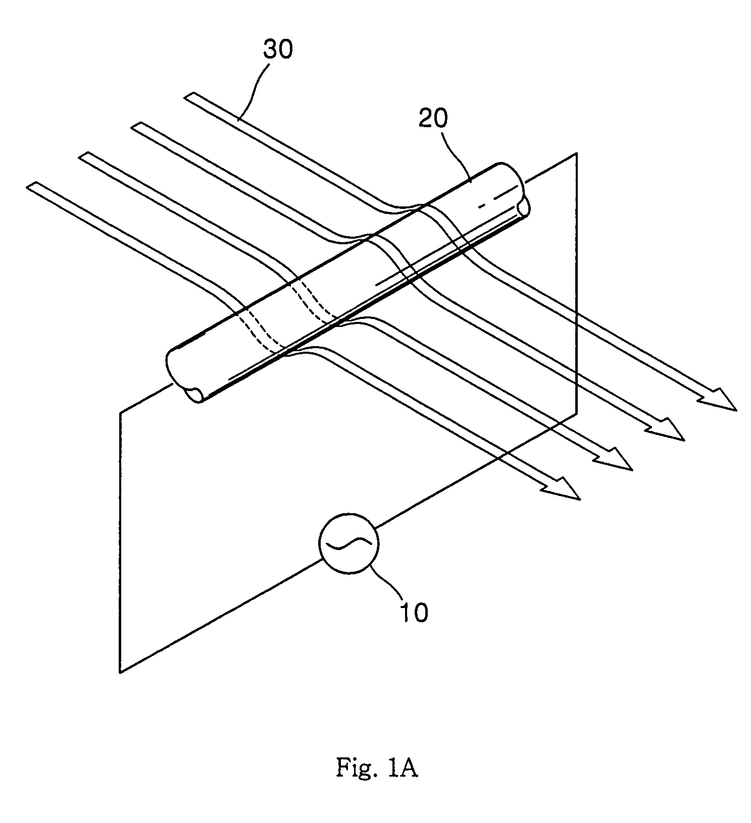
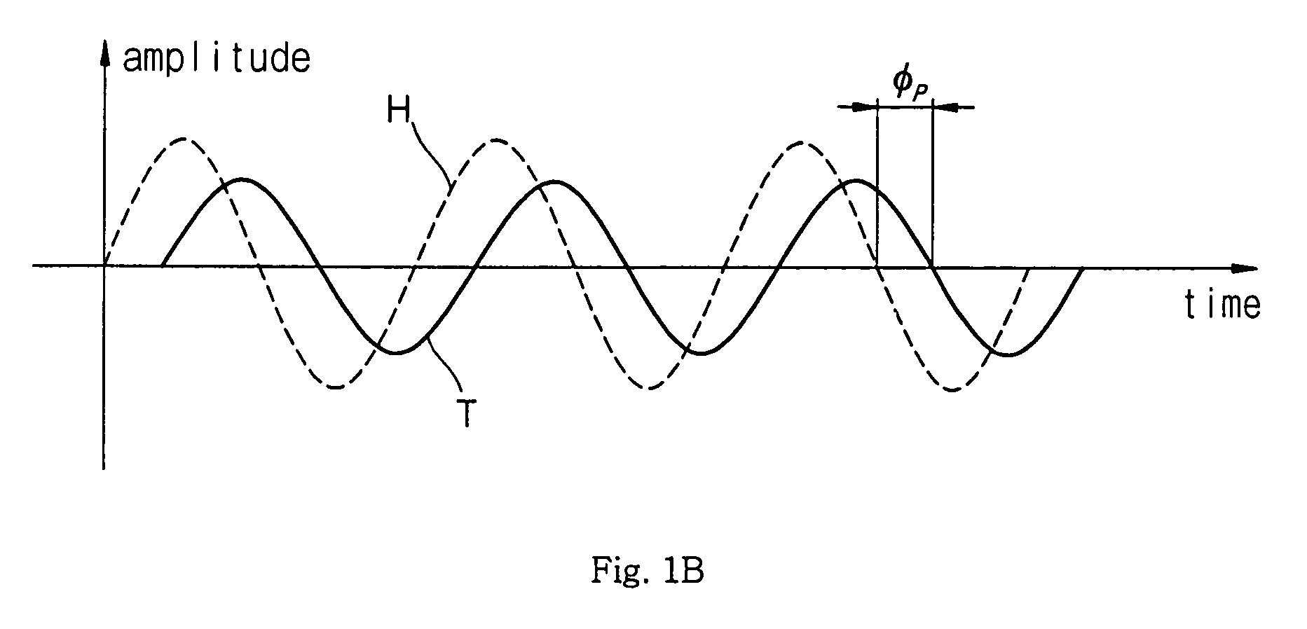
[0033]FIGS. 1A and 1B are schematic views showing the principle of measuring flow rate according to the present invention. As shown in FIG. 1A, when a resistive heater, such as a hotwire 20 supplied with AC power 10, is placed in a flow field 30, the hotwire 20 is periodically heated by AC power 10 supplied to the hotwire 20.

[0034]At this time, heat generation in the hotwire 20 shows a waveform H represented by a dotted line in FIG. 1B. The waveform H depends on the waveform of the supplied AC power 10. On the other hand, the temperature of the hotwire 20 oscillates with a certain phase lag φp relative to the periodic variation of heat generation. The waveform T expressed by a solid line of FIG. 1B represents the temperature variation of the hotwire 20. As shown in FIG. 1B, there is a phas...


PUM


Abstract

The present invention relates to a flowmeter suitable for a micro flow sensor. The flowmeter of the present invention comprises a resistive heater to be inserted into a fluid, AC power with a first frequency supplied to the resistive heater to periodically heat the resistive heater, a signal processing unit for detecting a first signal from the resistive heater in relation to a temperature variation of the resistive heater by the AC power, and obtaining a phase lag of the first signal relative to the heat generation in the resistive heater, and an operation unit for calculating a flow rate based on the obtained phage lag. According to the present invention, the flowmeter of the present invention has a wide measurement range and high measurement accuracy with a simple structure.

Description

BACKGROUND OF THE INVENTION[0001]1. Field of the Invention[0002]The present invention relates, in general, to an apparatus for measuring the flow rate of a fluid and, more particularly, to a flowmeter suitable for a micro flow sensor.[0003]2. Description of the Related Art[0004]Generally, the accurate measurement of a flow rate in microfluidic systems is very important in various applications, such as chemical component analyzing processes, the administration of medicine, and semiconductor fabrication processes. Micro flow sensors should have very simple structures because they should be installed in a very limited space and be easy to be integrated into microfabrication process of the microfluidic systems. Further, the micro flow sensors should have extremely high measurement accuracy because a flow rate in a micro channel is lower than that in a macro-scale channel. In the last 20 years, various micro flow sensors have been developed using micromachining technology. However, it is...

Claims


Application Information

Patent Timeline
Patent Type & Authority Patents(United States)
IPC IPC(8): G01F1/68G01P5/00G01F1/69G01F1/696G01F1/698
CPCG01F1/69G01F1/6986G01F1/696G01P5/00
Inventor KWON, OHMYOUNGLEE, JOON SIKCHOI, YOUNG KIPARK, SEUNGHOCHUNG, WON SEOK
Owner SEOUL NAT UNIV R&DB FOUND
Why Eureka
Try Eureka