Oil, water and gas separator for swaying service

Inactive Publication Date: 2006-03-07
EDMONDSON TECH HLDG
View PDF13 Cites 47 Cited by
  • Summary
  • Abstract
  • Description
  • Claims
  • Application Information

AI Technical Summary

Benefits of technology

[0005]This invention provides for a much more efficient processing performance than is normally produced by containment vessels of a similar vertical cylindrical shape with the common upward flow direction or the elongated cylindrical horizontal configuration when exposed to a swaying motion in as much as this invention in

Problems solved by technology

This is a very efficient arrangement when the vessels are anchored and level but has the disadvantage of a minor longitudinal tilting causing the upper and the lower stra

Method used


Image

  • Oil, water and gas separator for swaying service

Examples


Embodiment Construction

(Referring to the Figures)

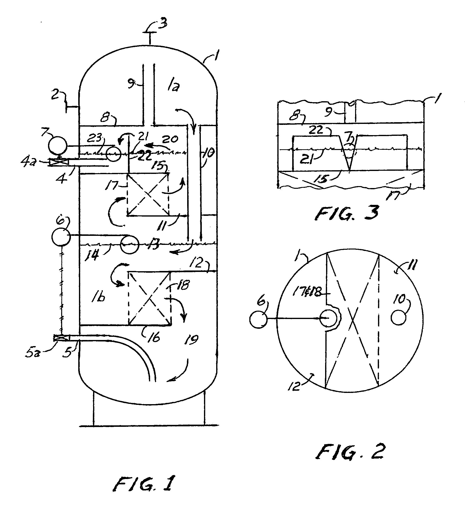
[0009]There is an enclosed vertical cylindrical containment vessel 1 with an inlet connection 2, a gas outlet connection 3, an oil outlet connection 4 with an oil discharge control valve 4a, a water outlet connection 5 with a water discharge control valve 5a, a water level sensor 6 and an oil level sensor 7. A solid circular baffle 8, to provide a confined space 1a wherein gas vapor is separated from the flowing oil and water liquid mixture, partitions an upper portion of the containment vessel. A pipe 10 serves as a conduit to deliver the flowing oil and water mixture into the lower chamber 1b wherein the liquid mixture is directed on a horizontal flow path. Semi-circular solid baffles 11 and 12 define a confined space 13 within which the oil and water interface 14 is established. Semi-circular solid baffles 15 and 16 serve to define a space in which the oil and water streams are directed on a horizontal flow path. To establish a plug flow of the oil and t...


PUM

PropertyMeasurementUnit
Forceaaaaaaaaaa
Gravityaaaaaaaaaa

Abstract

A cylindrical vertical oil, water and gas separator that incorporates the known advantage of a horizontal flow path, when utilizing the force of gravity to separate a mixture of flowing fluids into distinct laminar layers, while providing a means for maintaining the dynamic equilibrium of the disparate layers of the fluids even when the oil, water and gas separator is swaying back and forth as might happen if the oil, water and gas separator is installed on the deck of a ship.

Description

FIELD OF THE INVENTION[0001]This invention relates to apparatus and methods for processing a flowing mixture of oil, water and gas for the purpose of separating the oil water and gas into disparate components and cleaning each of the oil, water and gas components sufficiently for each to be delivered into oil, water and gas pipelines.BACKGROUND OF THE INVENTION[0002]The advantage of incorporating a horizontal flow path, as opposed to a vertical upward flow path, when using the force of gravity to separate oil, water and gas into disparate laminar layers is well known. With a vertical upward flow path the upward momentum presents a directly opposing force to the force of gravity, thus impeding the separation of the fluids much more than the resistance to the separation that is imposed when the flow is moving horizontally. To accomplish the horizontal flow path the containment vessels utilized are generally of an elongated horizontal cylindrical configuration with a length to diameter...

Claims


Application Information

Patent Timeline
IPC IPC(8): B01D17/028B01D17/00E21B43/34
CPCB01D17/00E21B43/34B01D17/0211B01D17/0214B01D17/045B01D17/12
Inventor EDMONDSON, JERRY M
Owner EDMONDSON TECH HLDG
Why Eureka
Try Eureka